

01
Nov
A Two-Channel Relay Module
Draft. This tutorial has not been checked against the physical product yet. Confirm wiring, pin assignments and voltage limits against the product documentation before building it.
| Difficulty | Advanced |
|---|---|
| Category | Motion |
| Supported boards | Arduino Uno R3 and compatible ATmega328P boards |
| Time needed | 50 minutes |
| Prerequisites | Switching Bigger Loads with a Relay |
| Tested board | Not yet verified |
| Tested on | Not yet verified |
| Arduino IDE version | Not yet verified |
| Library | Not yet verified |
What it does
Two relays on one board, so one Arduino can switch two separate loads. A fan and a lamp, a pump and an alarm, a heater and a light.
It is not simply “the single-channel board twice”. The Siratek part is a different design, and three of those differences matter enough that a reader who assumes otherwise will get it wrong.
Read this first
Everything in Switching Bigger Loads with a Relay applies here in full: the safety scoping to low-voltage DC, the warning about breadboards on the load side, and the startup problem. This page covers only what differs, so read that one first.
Difference 1: it has optocouplers
The single-channel board drives its relay coil straight from a transistor, with the coil sharing the Arduino’s ground. This board has optocouplers, the four-pin black packages visible beside the terminal block.
An optocoupler passes the signal as light across a gap, so the control side and the coil side are not electrically connected at all. That is real isolation, and it is why this board is the better choice for anything near a load that could misbehave.
But the isolation is only real if you use it, which is the next difference.
Difference 2: the yellow jumper decides whether the isolation exists
There is a small yellow jumper near the terminal block, bridging two of three pins usually marked JD-VCC, VCC and GND.
- Jumper fitted: the relay coils are powered from the Arduino’s 5 V, through the same wire as the logic. Convenient, and the optocouplers are bypassed as far as isolation goes, because both sides share a supply.
- Jumper removed, and a separate 5 V fed to
JD-VCC: the coils run from their own supply with their own ground. Now the optocouplers are doing their job, and a problem on the load side cannot reach the Arduino.
For a bench experiment, leave the jumper on. For anything permanent, take it off and give the coils their own supply. The board exists to make that possible, and leaving the jumper fitted throws that away.
Note also the current: two coils energised draw roughly 140 to 180 mA, which is a large share of what a USB port gives you. That alone is a reason to supply them separately.
Difference 3: check the coil voltage printed on the relays
The Siratek listing describes this as a 5 V module. The relays in the product photographs are marked JQC3F-12VDC-C, which is a 12 volt coil.
Those two statements disagree, and the 5 V and 12 V versions are physically identical apart from that printing.
Read the number on your own relays before connecting anything. A 12 V-coil board fed 5 V gives a relay that buzzes, clicks weakly, or does not pull in at all, and the fault looks like a dead board. A 5 V-coil board fed 12 V destroys the coils.
This is exactly the kind of thing a product photograph settles and a listing does not, and it is worth thirty seconds.
Difference 4: screw terminals for the control side too
The single-channel board has a three-pin header. This one has a four-way screw terminal block marked DC+, DC-, In1, In2.
That is more robust and slightly less convenient: jumper wires need tinning or ferrules to sit properly in a screw terminal. It also means there is no JD-VCC pin on a header, so the separate coil supply goes to the jumper block.
Difference 5: the trigger polarity is selectable
The single-channel board is low-level trigger only. This board’s silkscreen states that it supports both high and low level triggering, so the polarity depends on how the board is configured and which supply arrangement you chose.
Determine it experimentally rather than assuming, which takes one sketch and is the first thing the example below does. Name the result with a constant, as on the other page, so the rest of the sketch reads correctly whichever it turns out to be.
Before you begin
Required parts and tools
- An Arduino Uno or compatible board.
- One two-channel relay module. This is Siratek product 3398.
- A multimeter, to read the coil voltage and check continuity.
- A separate 5 V (or 12 V) supply for the coils, for anything beyond a bench test.
- Two low-voltage DC loads and their supply.
- A small screwdriver, and ferrules or tinned wire ends.
The contacts
Each channel has its own three-way screw terminal: NO, COM, NC. The relays are printed with their ratings, which in the photographs read 10 A 250 V AC and 10 A 30 V DC among others.
As on the single-channel page: “normally” means with no power on the coil, which includes every moment before your sketch runs. Decide per channel which state is safe and wire the load to that terminal.
Pin reference
| Terminal | Connect to | Purpose | Notes |
|---|---|---|---|
DC+ |
Uno 5V |
Logic supply | |
DC- |
Uno GND |
Ground | |
In1 |
Uno D7 |
Channel 1 control | Polarity determined below |
In2 |
Uno D8 |
Channel 2 control | |
JD-VCC block |
Own coil supply, jumper removed | Coil supply | For real isolation |
Channel 1 COM/NO/NC |
Load 1 | Contacts | Load side |
Channel 2 COM/NO/NC |
Load 2 | Contacts | Load side |
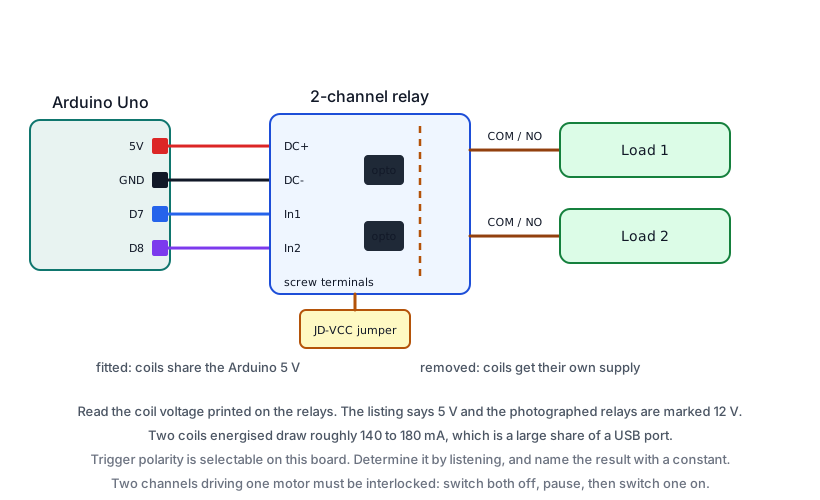
Wiring steps
- Unplug everything. Read the coil voltage printed on the relays.
- Control side only, nothing in the contact terminals yet:
DC-toGND,DC+to5V,In1toD7,In2toD8. - Leave the yellow jumper fitted for this first test.
- Plug in the USB cable and run the first sketch. You should hear each relay click in turn, with nothing connected to the load terminals at all.
- Only once that works, unplug and wire the loads.
Software and libraries
No library is required.
Minimal working example
Find the trigger polarity first.
// Siratek: which level turns these relays on?
// Listen. Nothing needs to be connected to the contacts.

const int in1 = 7;
const int in2 = 8;

void setup() {
  // Set the level before making the pins outputs, so they do not
  // pass through a state that clicks the relays on. See the
  // single-channel tutorial for why this order matters.
  digitalWrite(in1, HIGH);
  digitalWrite(in2, HIGH);
  pinMode(in1, OUTPUT);
  pinMode(in2, OUTPUT);

  Serial.begin(9600);
  Serial.println("Siratek: listening for clicks.");
}

void loop() {
  Serial.println("both HIGH");
  digitalWrite(in1, HIGH);
  digitalWrite(in2, HIGH);
  delay(2000);

  Serial.println("both LOW");
  digitalWrite(in1, LOW);
  digitalWrite(in2, LOW);
  delay(2000);
}
Listen to which half of the cycle produces the click, and watch the indicator LEDs. That tells you the polarity, and everything after it uses the answer.
Two channels, named properly
// Siratek: two independent loads, with the polarity named once.

const int in1 = 7;
const int in2 = 8;

// Set these from what you just heard.
const int RELAY_ON  = LOW;
const int RELAY_OFF = HIGH;

void setRelay(int pin, bool on) {
  digitalWrite(pin, on ? RELAY_ON : RELAY_OFF);
}

void setup() {
  digitalWrite(in1, RELAY_OFF);
  digitalWrite(in2, RELAY_OFF);
  pinMode(in1, OUTPUT);
  pinMode(in2, OUTPUT);

  Serial.begin(9600);
  Serial.println("Siratek: two channel relay.");
}

void loop() {
  Serial.println("channel 1 on");
  setRelay(in1, true);
  delay(3000);
  setRelay(in1, false);

  delay(1000);

  Serial.println("channel 2 on");
  setRelay(in2, true);
  delay(3000);
  setRelay(in2, false);

  delay(1000);
}
Note that the two channels are switched one at a time here, deliberately. Two coils energising together is the peak current, and if your supply is marginal that is the moment it will show.
Interlocking, which two channels make possible and necessary
Two relays introduce a failure the single-channel board cannot have: both on at once, when that must never happen.
The classic case is a motor driven forwards by one relay and backwards by the other. Both energised is a short across the supply.
// Siratek: two channels that must never be on together.

void setDirection(int which) {
  // Always switch both off first, and allow the contacts to settle.
  setRelay(in1, false);
  setRelay(in2, false);
  delay(50);

  if (which == 1) {
    setRelay(in1, true);
  } else if (which == 2) {
    setRelay(in2, true);
  }
}
The delay(50) is not decoration. Relay contacts take several milliseconds to open, and switching the second on before the first has released is exactly the condition you are preventing.
Where the consequence is serious, do it in hardware as well: wire the second relay’s coil through the first relay’s NC contact, so the board physically cannot energise both.
Expected result
Two audible clicks and two indicator LEDs following the sketch, with nothing in the contact terminals.
A relay that buzzes rather than clicking cleanly is being under-driven: either the coil voltage is wrong for the supply, or the supply cannot deliver the coil current.
Troubleshooting
| Symptom | Likely cause | Check or fix |
|---|---|---|
| Relays buzz or click weakly | 12 V coils on a 5 V supply | Read the printing on the relays |
| Coils destroyed | 5 V coils on 12 V | Same check, before connecting |
| Neither channel responds | Trigger polarity assumed | Run the first sketch and listen |
| Board resets the Arduino | Two coils on USB power | Separate coil supply, jumper removed |
| Isolation not working as expected | Jumper still fitted | Remove it and feed JD-VCC separately |
| Relays click at reset and during upload | Pins floating before setup() |
Set the level before pinMode() |
| Jumper wires fall out | Screw terminals, not a header | Tin the ends or use ferrules |
| One channel works, the other does not | Wrong pin, or a loose terminal | Swap the two wires and see which follows |
| Both on at once in a motor circuit | No interlock | Switch both off first, with a delay |
| Load does nothing though the relay clicks | Wired to NC instead of NO |
Check which terminal |
| Anything unexpected on the load side | Stop | Disconnect the load supply first |
Next steps
- Easier first: Switching Bigger Loads with a Relay, which this page assumes throughout.
- Related products: the submersible pump and the mini electronic lock, both of which this board is intended to switch.
- Next project: a gas leak alarm, where one channel sounds a warning and the other cuts something off.
Sources and attribution
All text, wiring guidance and code in this tutorial are original Siratek work.
- The optocouplers, the
DC+ DC- In1 In2screw terminal, the coil-supply jumper, the two three-way contact terminals and theJQC3F-12VDC-Crelay marking were all read from the Siratek product photographs for item 3398. The silkscreen also states that the board supports both high and low level triggering. - The safety scoping and the startup behaviour are as set out in Switching Bigger Loads with a Relay.
The product listing describes a 5 V module while the photographed relays are marked 12 V. That discrepancy is reported here rather than resolved, because only the part in the reader’s hand can settle it, and the bench session should record which is actually supplied. No third-party tutorial text, diagrams, photographs or code has been reproduced here.