

01
Nov
Switching Bigger Loads with a Relay
Draft. This tutorial has not been checked against the physical product yet. Confirm wiring, pin assignments and voltage limits against the product documentation before building it.
| Difficulty | Advanced |
|---|---|
| Category | Motion |
| Supported boards | Arduino Uno R3 and compatible ATmega328P boards |
| Time needed | 60 minutes |
| Prerequisites | Powering Your Project |
| Tested board | Not yet verified |
| Tested on | Not yet verified |
| Arduino IDE version | Not yet verified |
| Library | Not yet verified |
What it does
A relay is a mechanical switch operated by an electromagnet. A small current through the coil pulls a set of contacts together, and those contacts can carry far more current than the coil ever touches, on a circuit that has nothing electrically to do with the one controlling it.
That last part is the whole point. It is how a 5 V microcontroller switches a 12 V pump, a 24 V solenoid, or a lamp.
The module adds the parts that make a relay usable from a logic pin: a transistor to drive the coil, a flyback diode across it, indicator LEDs, and screw terminals for the load.
Safety first, and this one is not boilerplate
Every other tutorial in this library works at 5 V, where a mistake costs a component. A relay is the first part where a mistake can cost a great deal more, so read this section before you wire anything.
This tutorial uses a low-voltage DC load throughout. A 12 V lamp, a small pump, a buzzer, a motor on its own supply. Everything below is written for that, and that is what you should build first.
On switching mains. The contacts on this part are rated for it, and people do use these modules that way. It is not a beginner project and it is not something to improvise on a breadboard. Mains work needs, at minimum: a proper enclosure with no exposed conductors, correct cable and terminal sizing, strain relief, switching of the live conductor rather than the neutral, and in most cases a qualified electrician. In Ghana the supply is around 230 V, which is enough to kill. If you are not confident you can meet all of that, switch a low-voltage load instead, or use a commercial mains-rated smart switch and control that.
This module gives you no isolation between the Arduino and the coil. Look at the board: there is a transistor and a diode, but no optocoupler and no separate JD-VCC supply jumper. The coil circuit shares the Arduino’s ground. The relay’s contacts are still isolated from everything on the low-voltage side, which is the protection that matters for the load, but the control side is not isolated from your board or from the computer the USB cable is plugged into. Modules with an optocoupler and a separate coil supply exist and are the right choice for anything near mains.
Never breadboard the load side. Breadboard contacts are rated for a fraction of an amp and are not meant to be touched while live. Load wiring belongs in the screw terminals, tightened properly, with the insulation reaching the terminal.
Treat the terminal block as live whenever the load supply is connected, regardless of what the relay is doing or what your code says.
Before you begin
Required parts and tools
- An Arduino Uno or compatible board.
- One 1-channel 5 V relay module, low level trigger. This is Siratek product 3308.
- Three jumper wires.
- A low-voltage DC load and its own supply. A 12 V lamp and a 12 V supply is a good first choice.
- A small screwdriver for the terminals.
What is on the board
- A blue TONGLING JQC-3FF-S-Z relay with a 5 V DC coil. The case is printed with its contact ratings; read the ones on your own part rather than trusting a figure from a tutorial.
- A three-pin header marked
VCC,GND,IN. - A three-way screw terminal block: normally open, common, normally closed.
- Two LEDs. One is marked
PWRand lights whenever the board has 5 V. The other follows the relay, so you can see the state without a meter. - A transistor, a resistor and a flyback diode. No optocoupler, as noted above.
Normally open and normally closed
The three screw terminals are:
- COM, the common pole, usually the middle one.
- NO, normally open. Not connected to COM while the relay is at rest; connected when energised.
- NC, normally closed. The reverse.
“Normally” means with no power on the coil, which includes every moment before your sketch starts, while it is uploading, and after a crash.
That makes the choice a safety decision rather than a convenience. Ask what should happen if the Arduino loses power, and wire the load to the terminal that gives that answer. A lamp that should go dark goes on NO. A ventilation fan that should keep running goes on NC.
Low level trigger, which changes the code
The Siratek part is a low level trigger module. IN pulled LOW energises the relay; HIGH releases it.
This inverts what most example sketches assume, and it creates a specific problem at startup.
When the Uno resets, every pin is an input and floats. The module’s IN sees no clear HIGH, the transistor turns on, and the relay clicks closed before your sketch has run a line. It stays that way through the whole bootloader delay, roughly a second, and on every reset and every upload.
If the relay is switching a lamp, that is a flicker. If it is switching a pump or a heater, it is not.
The fix is one line, in the right order:
digitalWrite(relayPin, HIGH);  // set the state first
pinMode(relayPin, OUTPUT);     // then drive the pin
Writing HIGH to a pin that is still an input sets the output register, so that the instant pinMode() makes it an output, it is already HIGH. Do it the usual way round and the pin spends a few microseconds LOW, which is enough for the relay to click.
That does not cover the bootloader delay before setup() runs, and nothing in software can. Where an unintended switch-on would be dangerous, wire the load so that de-energised is the safe state.
How much current the coil takes
The coil of a JQC-3FF-S-Z draws somewhere around 70 to 90 mA at 5 V. That current comes out of whatever is feeding VCC.
On USB power, with one relay and nothing else, that is acceptable. It is a large fraction of your budget, though, and two relays plus a display will not fit. See Powering Your Project for working that out. A multi-channel relay board should have its own supply.
Pin reference
| Pin or terminal | Connect to | Purpose | Notes |
|---|---|---|---|
VCC |
Uno 5V |
Coil and logic power | Roughly 70 to 90 mA when energised |
GND |
Uno GND |
Ground | Shared with the coil circuit |
IN |
Uno D7 |
Control | LOW energises on this board |
COM |
Load supply positive | Common pole | Load side, screw terminal |
NO |
Load positive lead | Closed only when energised | Use for “off when unpowered” |
NC |
Not used in this example | Closed when at rest | Use for “on when unpowered” |
The load’s negative lead goes back to its own supply’s negative, not through the module and not to the Arduino.
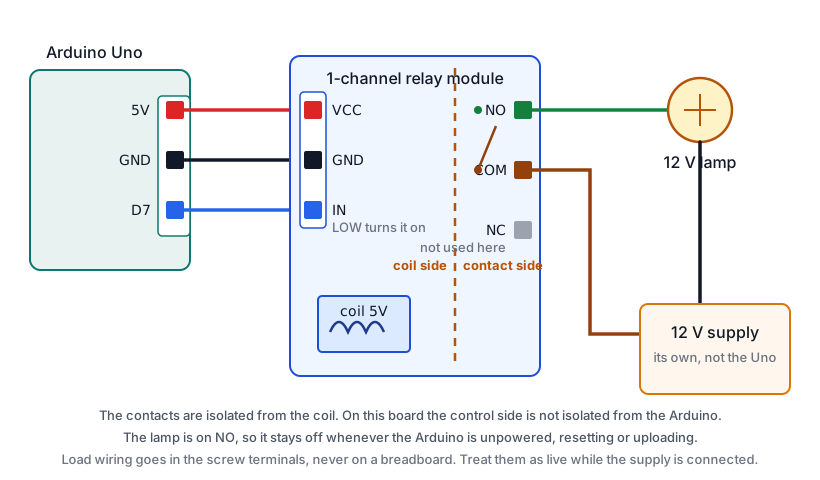
Wiring steps
Do the control side first, prove it works with nothing connected to the terminals, and only then wire the load.
- Unplug the USB cable. Make sure the load supply is disconnected.
GNDto the Uno’sGND.VCCto the Uno’s5V.INtoD7.- Plug in the USB cable. The
PWRLED should light. Upload the sketch below and listen: you should hear the relay click, and see the second LED follow it. This is the test, and it needs no load at all. - Unplug the USB cable again.
- Wire the load: supply positive into
COM, the load’s positive lead intoNO, and the load’s negative lead back to the supply negative. - Tighten every screw terminal properly and check that no bare conductor is showing.
- Plug in the USB cable, then connect the load supply.
Software and libraries
No library is required.
Minimal working example
// Siratek: switching a low-voltage load with a low-trigger relay module.
// On this board, LOW energises the relay.

const int relayPin = 7;

// Named so the code reads correctly whichever board you have.
const int RELAY_ON = LOW;
const int RELAY_OFF = HIGH;

void setup() {
  // Set the level before making the pin an output, so it never
  // passes through LOW and clicks the relay on.
  digitalWrite(relayPin, RELAY_OFF);
  pinMode(relayPin, OUTPUT);

  Serial.begin(9600);
  Serial.println("Siratek: relay test starting, off.");
}

void loop() {
  Serial.println("on");
  digitalWrite(relayPin, RELAY_ON);
  delay(3000);

  Serial.println("off");
  digitalWrite(relayPin, RELAY_OFF);
  delay(3000);
}
The two constants are worth keeping even though they look like noise. A high-trigger module needs only those two lines changed, and every other line in the sketch still reads the way it behaves.
Do not switch it quickly
A relay is mechanical. Its contacts are rated for a large but finite number of operations, perhaps a hundred thousand under load, and each switch under current erodes them a little.
So a relay is for things that change state occasionally: a pump that runs for ten minutes, a light on at dusk. It is not for dimming, not for PWM, and not for anything that might chatter.
Chattering is the failure to watch for. A sensor reading sitting exactly on a threshold will switch the relay on and off many times a second, which sounds alarming, wears the contacts out quickly, and can damage the load. The two defences are hysteresis and a minimum dwell time.
// Siratek: switching on a sensor reading, without chattering.

const int relayPin = 7;
const int sensorPin = A0;

const int RELAY_ON = LOW;
const int RELAY_OFF = HIGH;

// Two thresholds with a gap between them, not one.
const int turnOnBelow = 380;
const int turnOffAbove = 420;

// Once switched, hold that state for at least this long.
const unsigned long minimumDwell = 10000;

bool isOn = false;
unsigned long lastSwitch = 0;

void setup() {
  digitalWrite(relayPin, RELAY_OFF);
  pinMode(relayPin, OUTPUT);
  Serial.begin(9600);
}

void loop() {
  int reading = analogRead(sensorPin);

  if (millis() - lastSwitch >= minimumDwell) {
    if (!isOn && reading < turnOnBelow) {
      isOn = true;
      lastSwitch = millis();
      digitalWrite(relayPin, RELAY_ON);
      Serial.println("relay on");
    } else if (isOn && reading > turnOffAbove) {
      isOn = false;
      lastSwitch = millis();
      digitalWrite(relayPin, RELAY_OFF);
      Serial.println("relay off");
    }
  }

  delay(100);
}
The gap between 380 and 420 means a reading wavering by a few counts cannot flip the state. The dwell time means that even a large swing cannot cycle the load faster than once every ten seconds. Both are needed; neither alone is enough.
Expected result
A click you can hear and an LED that follows it, three seconds on and three seconds off, with nothing connected to the screw terminals.
With a load connected, the same, plus the load switching. The relay should click once per change and then be silent. A buzzing or rapidly clicking relay means the coil is not getting a clean 5 V, usually because the supply cannot provide the coil current.
Troubleshooting
| Symptom | Likely cause | Check or fix |
|---|---|---|
| Relay clicks on at reset and during upload | Pin floating before setup() |
Set the level before pinMode(); wire the safe state to the right terminal |
| Logic inverted from the examples you have seen | This board is low trigger | LOW energises; use the named constants |
No click at all, PWR LED off |
VCC or GND not connected |
Check both before anything else |
No click, PWR LED on |
IN on the wrong pin |
Check against relayPin |
| Buzzes or clicks repeatedly | Coil current beyond the supply | Give the module its own 5 V, grounds joined |
| Arduino resets when the relay switches | Same cause | Separate supply for the coil |
| Clicks, but the load does nothing | Load on NC instead of NO |
Check which terminal you used |
| Load is on when the Arduino is off | Load wired to NC |
That may be what you want; decide deliberately |
| Switches on and off constantly | Sensor sitting on the threshold | Add hysteresis and a dwell time |
| Contacts stop working after a while | Worn by switching under load | Expected eventually; relays are consumable |
| Anything at all unexpected on the load side | Stop | Disconnect the load supply before investigating |
Next steps
- Easier first: Powering Your Project, for the current budget this module eats into.
- Related product: a multi-channel relay board, when more than one load needs switching. Give it its own supply.
- Next project: an automatic plant watering system, where a soil moisture reading switches a pump. Build it with a low-voltage pump.
Sources and attribution
All text, wiring guidance and code in this tutorial are original Siratek work.
- The board described here, a single-channel low level trigger module with a
VCCGNDINheader, a three-way screw terminal, aPWRLED and a transistor-driven coil with no optocoupler, was read from the Siratek product photographs for item 3308, together with the TONGLING JQC-3FF-S-Z marking on the relay case. - Arduino core documentation for pin behaviour at reset, which is the basis of the startup note.
Coil current and contact life are given as typical figures for this relay family and vary between parts; the reader is told to read the ratings printed on their own relay. The safety guidance here scopes the tutorial to low-voltage DC loads and is not a substitute for a qualified electrician where mains is involved. No third-party tutorial text, diagrams, photographs or code has been reproduced here.