

01
Nov
Project, an RFID Door Lock
Draft. This tutorial has not been checked against the physical product yet. Confirm wiring, pin assignments and voltage limits against the product documentation before building it.
| Difficulty | Advanced |
|---|---|
| Category | Projects |
| Supported boards | Arduino Uno R3 and compatible ATmega328P boards |
| Time needed | 150 minutes |
| Prerequisites | A Mini Electronic Lock |
| Tested board | Not yet verified |
| Tested on | Not yet verified |
| Arduino IDE version | Not yet verified |
| Library | Not yet verified |
What you will build
A cabinet that opens when you present a card. A reader on the outside, a solenoid latch on the inside, a release button, and a list of accepted cards that survives being unplugged — with a master card that adds and removes cards without a computer.
Read this first: what this is for
Two limits, both from the component pages, and both of which decide where this project may be fitted.
A card’s UID is not a password. Reading RFID Cards with an RC522 puts it plainly: a UID can be read by anybody with a reader, blank cards that let you write any UID you like are cheap, and MIFARE Classic’s own encryption has been thoroughly broken in published research. Anyone who can stand near your card for a second can make one that opens this.
The lock is fail-secure, and it is a small latch. With no power the bolt stays out, so a power cut leaves it shut. A Mini Electronic Lock says what follows from that: it suits a cabinet, a drawer, a store room or a workshop cupboard, and it must not go on a door that a person might need to get out through, or anything on a fire escape route. The latch itself is a spring bolt in thin metal held by four screws — it resists a casual pull and not much more.
So: a convenient cabinet that opens to a card. That is a genuinely useful thing and it is what this project is. It is not an access control system, and anyone you build one for should be told the same.
Before you begin
Parts
| Part | Siratek product | Its own tutorial |
|---|---|---|
| Arduino Uno | 2219 | Getting Started with Arduino Uno |
| RC522 reader with card and fob | 2609 | Reading RFID Cards with an RC522 |
| Mini electronic lock | 2795 | A Mini Electronic Lock |
| Relay module | 3308 | Switching Bigger Loads with a Relay |
| Green and red LEDs with 220 ohm resistors | 2234 | Your First Circuit, an LED and a Resistor |
| Active buzzer | 2520 | Active Buzzer, a Beep Without Code |
| Push button | 2353 | Read a Push Button |
| Breadboard and jumper wires | Using a Breadboard |
Also needed: a DC supply for the lock, a 1N4007 diode, and a multimeter.
Settle the lock’s supply before anything else
The Siratek lock has no voltage printed on it anywhere. These are commonly 12 V, and 6 V versions exist, and guessing is how you destroy one.
Measure the coil resistance across its two wires, then current = voltage / resistance. A coil reading 20 ohms draws 0.6 A at 12 V; one reading 7 ohms draws 1.7 A, which is a very different supply. Expect somewhere between 0.5 and 1.5 amps, which is far beyond anything the Arduino can give and the reason the relay is here.
The full procedure is on the lock’s own page. Do it first.
The lock must only ever be energised briefly
The coil has no thermal protection. Held on, it becomes too hot to touch within about a minute and can be damaged permanently.
Every sketch here energises for one and a half seconds and has a hard ceiling checked independently of whatever decided to open the lock. If you take one habit from this project, take that one: on a part that can be destroyed by being left on, the limit must not consult the logic that might be wrong.
3.3 volts, and a pin that looks ordinary
The RC522’s supply pin is 3.3 V. Five volts there destroys the reader, and the pin sits in a row of eight that all look alike. Check it twice before powering up; this is the single most common way these modules die.
Its SPI pins are 5 V signals going into a 3.3 V part, which works on a bench and is out of specification. For something that will live on a cabinet door, put a level converter on MOSI and SCK. Mixing 3.3 V and 5 V Safely is the page.
What happens at power-up, which is a safety question
When the board resets, every pin starts as a floating input. If the relay’s resting level is the one that energises the lock, the lock pulses open at every reset — and on a cabinet lock that is a security hole you cannot see, because it lasts a fraction of a second.
The sketch writes the resting level before pinMode() makes the pin an output, which is the order that avoids the pulse. Test it deliberately: press the reset button with the lock connected and watch the bolt.
How it works
The card list lives in EEPROM, so it survives a power cut, and three states keep the lock honest:
| State | What it means | What ends it |
|---|---|---|
IDLE |
Waiting for a card | A card, or the release button |
OPEN |
Lock energised | The open time, or the hard ceiling |
ENROLLING |
Master card presented; next card is added or removed | A card, or thirty seconds |
The decision is deliberately boring:
- A card arrives. Its UID is read.
- If it is the master card, go to
ENROLLING. - If it is in the list, open.
- If it is not, refuse — and if refusals keep coming, slow down.
- Whatever happened, the lock closes on time.
Enrolment without a computer
A cabinet whose card list can only be changed by editing a sketch is a cabinet you will stop using.
So one card is the master. Present it, and the next card presented is added to the list — or, if it is already in the list, removed from it. A beep pattern says which happened, and after thirty seconds with no card the mode gives up on its own.
The master card never opens the lock. That is a small decision with a real consequence: the card you carry to administer the thing is not the card you carry to use it, so losing one does not lose both.
Why the refusal counter exists, and what it does not fix
After five refused cards in a row the project waits thirty seconds before reading another, and says so on its red LED.
Be clear about what this achieves. It makes trying thousands of random UIDs impractical. It does nothing against the real attack, which is cloning a card that is already accepted. It is worth the eight lines anyway, in the same way a lock on a garden gate is worth having, but it does not change the paragraph at the top of this page.
EEPROM, and writing to it sparingly
An ATmega328P’s EEPROM is good for roughly 100,000 writes per cell. That is plenty for a list that changes when somebody is given a card, and nothing like enough for something written every time the lock opens.
So the list is written only on enrolment, and the open count is not stored at all. If you want a log of every opening, that belongs on an SD card — see Making it yours.
Build it in stages
Stage 1: the reader, nothing else
Wire the RC522 and run its tutorial’s example. Present the card and the fob and write their UIDs down. You need one of them to be the master, and you cannot set the master without knowing a UID.
If the reader is not found, the cause is 3.3V or a wrong SPI pin, in that order of likelihood.
Stage 2: the indicators
Green LED, red LED and the buzzer, with the reader logic still just printing. Accepted and refused should be unmistakable across a room.
Stage 3: the relay and the lock, on the bench
Wire the relay’s control side only and hear it click. Then the load side, with the diode, with the lock’s own supply, grounds joined.
Clamp the lock or hold it. It jumps when it fires, and the impulse is sharper than you expect.
Then press the Arduino’s reset button, repeatedly, and watch the bolt. It must not move. If it twitches, your relay’s resting level is wrong and the project is not ready for a cabinet door.
Stage 4: put it together
The complete sketch below. Set MASTER_UID to one of the UIDs you wrote down in stage 1.
Stage 5: fit it, and only to the right thing
Four screws, a cabinet or a drawer, the striker plate aligned so the bolt drops in cleanly. Put the reader on the outside and everything else on the inside, including the release button — a release button on the outside is a lock with a button that opens it.
Pin reference
| Device | Pin | Connect to | Notes |
|---|---|---|---|
| RC522 | 3.3V |
Uno 3.3V |
Never 5V |
| RC522 | GND |
Uno GND |
|
| RC522 | RST |
Uno D9 |
|
| RC522 | SDA |
Uno D10 |
SPI chip select, not I2C |
| RC522 | MOSI |
Uno D11 |
Converter for a permanent build |
| RC522 | MISO |
Uno D12 |
|
| RC522 | SCK |
Uno D13 |
Converter for a permanent build |
| Green LED | anode | Uno D5 |
Through 220 ohms |
| Red LED | anode | Uno D6 |
Through 220 ohms |
| Relay | IN |
Uno D7 |
LOW energises on this board |
| Relay | VCC, GND |
Uno 5V, GND |
|
| Buzzer | + |
Uno D8 |
|
| Release button | one leg | Uno D2 |
INPUT_PULLUP, inside |
| Relay | COM |
Lock supply + |
Load side |
| Relay | NO |
Lock red | Locked when unpowered |
| Lock | black | Lock supply - |
|
| Diode | across the lock | Banded end to red | 1N4007, required |
| Lock supply | - |
Also Uno GND |
Shared reference |
D13 is the SPI clock here, so the onboard LED flickers while the reader is being polled. That is the bus working, not a fault, and it is why the indicators are on D5 and D6.
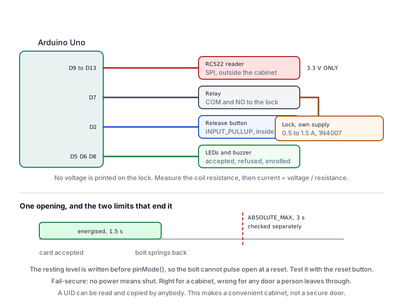
The complete sketch
// Siratek: an RFID cabinet lock.
// See the top of the page for what a UID is and is not.

#include <SPI.h>
#include <MFRC522.h>
#include <EEPROM.h>

MFRC522 reader(10, 9);

const int greenPin  = 5;
const int redPin    = 6;
const int lockPin   = 7;
const int buzzerPin = 8;
const int buttonPin = 2;

// Relay polarity: see Switching Bigger Loads with a Relay.
const int LOCK_ENERGISED = LOW;
const int LOCK_RESTING   = HIGH;

const unsigned long OPEN_FOR     = 1500;    // the bolt is in for this long
const unsigned long ABSOLUTE_MAX = 3000;    // and never longer than this
const unsigned long ENROL_WINDOW = 30000;

// ---- From stage 1. The master administers; it never opens. ----
const byte MASTER_UID[4] = {0xDE, 0xAD, 0xBE, 0xEF};
// ---------------------------------------------------------------

// EEPROM layout: a marker, a count, then up to 8 four-byte UIDs.
const int EEPROM_MARKER_ADDR = 0;
const int EEPROM_COUNT_ADDR  = 1;
const int EEPROM_LIST_ADDR   = 2;
const byte MARKER = 0x5A;
const int MAX_CARDS = 8;

enum State { IDLE, OPEN, ENROLLING };
State state = IDLE;
unsigned long stateSince = 0;

int refusals = 0;
unsigned long lockedOutUntil = 0;

void beep(int times, int lengthMs) {
  for (int i = 0; i < times; i++) {
    digitalWrite(buzzerPin, HIGH);
    delay(lengthMs);
    digitalWrite(buzzerPin, LOW);
    if (i < times - 1) {
      delay(lengthMs);
    }
  }
}

byte cardCount() {
  if (EEPROM.read(EEPROM_MARKER_ADDR) != MARKER) {
    return 0;                       // never initialised
  }
  byte n = EEPROM.read(EEPROM_COUNT_ADDR);
  return n > MAX_CARDS ? 0 : n;
}

void readCard(byte index, byte out[4]) {
  for (byte i = 0; i < 4; i++) {
    out[i] = EEPROM.read(EEPROM_LIST_ADDR + index * 4 + i);
  }
}

bool sameUid(const byte a[4], const byte b[4]) {
  for (byte i = 0; i < 4; i++) {
    if (a[i] != b[i]) {
      return false;
    }
  }
  return true;
}

// -1 if not in the list, otherwise its index.
int findCard(const byte uid[4]) {
  byte n = cardCount();
  byte stored[4];
  for (byte i = 0; i < n; i++) {
    readCard(i, stored);
    if (sameUid(stored, uid)) {
      return i;
    }
  }
  return -1;
}

bool addCard(const byte uid[4]) {
  byte n = cardCount();
  if (n >= MAX_CARDS) {
    return false;
  }
  for (byte i = 0; i < 4; i++) {
    EEPROM.update(EEPROM_LIST_ADDR + n * 4 + i, uid[i]);
  }
  EEPROM.update(EEPROM_COUNT_ADDR, n + 1);
  EEPROM.update(EEPROM_MARKER_ADDR, MARKER);
  return true;
}

void removeCard(int index) {
  byte n = cardCount();
  byte moved[4];
  // Move the last one into the gap, then shorten the list.
  if (index != n - 1) {
    readCard(n - 1, moved);
    for (byte i = 0; i < 4; i++) {
      EEPROM.update(EEPROM_LIST_ADDR + index * 4 + i, moved[i]);
    }
  }
  EEPROM.update(EEPROM_COUNT_ADDR, n - 1);
}

void release() {
  digitalWrite(lockPin, LOCK_RESTING);
  digitalWrite(greenPin, LOW);
  state = IDLE;
  stateSince = millis();
}

void openLock(const __FlashStringHelper* why) {
  if (state == OPEN) {
    return;                         // already open; do not extend it
  }
  state = OPEN;
  stateSince = millis();
  digitalWrite(lockPin, LOCK_ENERGISED);
  digitalWrite(greenPin, HIGH);
  beep(1, 80);
  Serial.print(F("open: "));
  Serial.println(why);
}

void refuse() {
  refusals++;
  digitalWrite(redPin, HIGH);
  beep(2, 60);
  delay(400);
  digitalWrite(redPin, LOW);

  Serial.print(F("refused ("));
  Serial.print(refusals);
  Serial.println(F(")"));

  if (refusals >= 5) {
    lockedOutUntil = millis() + 30000UL;
    refusals = 0;
    Serial.println(F("too many refusals: pausing for 30 seconds"));
  }
}

void setup() {
  // The resting level FIRST, so the lock cannot pulse on at reset.
  digitalWrite(lockPin, LOCK_RESTING);
  pinMode(lockPin, OUTPUT);

  pinMode(greenPin, OUTPUT);
  pinMode(redPin, OUTPUT);
  pinMode(buzzerPin, OUTPUT);
  pinMode(buttonPin, INPUT_PULLUP);

  Serial.begin(9600);
  SPI.begin();
  reader.PCD_Init();

  Serial.print(F("Siratek: cabinet lock. Cards enrolled: "));
  Serial.println(cardCount());
  stateSince = millis();
}

void loop() {
  // 1. The limits. Checked before anything else, and they read only the clock.
  if (state == OPEN && millis() - stateSince >= OPEN_FOR) {
    release();
    Serial.println(F("closed"));
  }
  if (state == OPEN && millis() - stateSince >= ABSOLUTE_MAX) {
    release();
    Serial.println(F("closed: absolute limit"));
  }

  // 2. Enrolment gives up on its own.
  if (state == ENROLLING && millis() - stateSince >= ENROL_WINDOW) {
    state = IDLE;
    digitalWrite(redPin, LOW);
    Serial.println(F("enrolment timed out"));
  }

  // 3. The release button, on the inside.
  if (digitalRead(buttonPin) == LOW && state != OPEN) {
    openLock(F("release button"));
    return;
  }

  // 4. Refusal lockout.
  if (millis() < lockedOutUntil) {
    digitalWrite(redPin, (millis() % 1000) < 500);
    return;
  }

  // 5. A card, or nothing.
  if (!reader.PICC_IsNewCardPresent() || !reader.PICC_ReadCardSerial()) {
    return;
  }

  if (reader.uid.size != 4) {
    // Seven-byte UIDs are common on newer cards and phones. This list
    // holds four-byte ones, and comparing only the first four would
    // accept cards it should not.
    Serial.println(F("refused: not a 4-byte UID"));
    refuse();
    reader.PICC_HaltA();
    reader.PCD_StopCrypto1();
    return;
  }

  byte uid[4];
  for (byte i = 0; i < 4; i++) {
    uid[i] = reader.uid.uidByte[i];
  }

  if (state == ENROLLING) {
    int found = findCard(uid);
    if (found >= 0) {
      removeCard(found);
      beep(3, 70);
      Serial.println(F("card removed"));
    } else if (addCard(uid)) {
      beep(2, 150);
      Serial.println(F("card added"));
    } else {
      beep(5, 50);
      Serial.println(F("list full"));
    }
    state = IDLE;
    digitalWrite(redPin, LOW);

  } else if (sameUid(uid, MASTER_UID)) {
    state = ENROLLING;
    stateSince = millis();
    digitalWrite(redPin, HIGH);
    beep(1, 300);
    Serial.println(F("master: present a card to add or remove it"));

  } else if (findCard(uid) >= 0) {
    refusals = 0;
    openLock(F("known card"));

  } else {
    refuse();
  }

  reader.PICC_HaltA();
  reader.PCD_StopCrypto1();
}
Five decisions worth explaining
The resting level is written before pinMode(). One line in an unusual order, and it is the difference between a cabinet that stays shut through a reset and one that flicks open every time the power wavers. Test it rather than trusting it.
Two independent time limits. OPEN_FOR is the normal one; ABSOLUTE_MAX exists in case something is wrong with the first. On a coil that can be destroyed by being left on, that redundancy costs four lines.
openLock() refuses to extend an open that is already running. Without that, a card held against the reader or a stuck button would keep pushing the timestamp forward and the lock would stay energised indefinitely — exactly what must not happen.
The limits are the first thing in loop(), before the button and before the reader. So a card presented during an open cannot delay the close, and neither can anything else.
EEPROM.update(), not EEPROM.write(). update() only writes when the byte is actually different, which matters on a part rated for about 100,000 writes per cell.
Testing it
| Try this | It should |
|---|---|
| Press the Arduino’s reset with the lock connected | The bolt must not move at all |
| Present an unknown card | Red, two beeps, nothing opens |
| Present the master, then an unknown card | Two long beeps: added |
| Present that card | Opens |
| Present the master, then that same card | Three beeps: removed |
| Present it again | Refused |
| Unplug everything, plug it back in | The list is still there; the count prints at startup |
| Present the master card alone | Enrolment mode, then it gives up after thirty seconds |
| Hold a known card against the reader | Opens once, closes on time, does not re-open while held |
| Five unknown cards in a row | Red blinks, reader ignored for thirty seconds |
| Press the release button | Opens |
| Energise it, then pull the lock’s supply | The bolt springs out at once: fail-secure |
| Feel the lock after ten operations | Cool. Warm means the limits are not working |
The first and the last-but-one are the two that matter. One proves the lock cannot be opened by interrupting the power; the other proves it closes when the power goes. Both are properties of the build rather than the code, and both are worth demonstrating to whoever will use the cabinet.
Making it yours
- Log every opening. The SD card module and the DS3231 give a dated line per card, which is the single most useful addition: not security, but a genuine record of who opened what and when. Project, a Standalone Data Logger is the pattern, and it keeps those writes off the EEPROM.
- Add a keypad. A card and a four-digit code is meaningfully better than a card alone, because cloning the card is then not enough. The 4×4 keypad page covers it.
- A fingerprint sensor instead. Nothing to clone and nothing to lose, with its own limits set out on its page. The lock side of this project is unchanged.
- Show something. A 16×2 I2C LCD saying “present card”, “welcome” or “enrolment” makes the project explain itself to someone who has never seen it.
- Put the reader on a door and the brain inside. A long cable to the reader is the right arrangement; a long cable to the lock is not, because a cut cable at the lock end is a way in.
What not to do: fit this to a room door, a front door, or anything on an escape route. Fail-secure plus a spring latch plus a cloneable card is the wrong combination for all three.
Troubleshooting
| Symptom | Likely cause | Check or fix |
|---|---|---|
| Reader not found at startup | 3.3V, or SPI wiring |
Never 5V; SDA is D10, RST is D9 |
| Reader worked once, now dead | 5 V applied to it | That board is 3.3 V only |
| Cards read intermittently | PCD_StopCrypto1() missing |
It is at the end of every path |
| Bolt twitches at reset | Resting level set after pinMode |
Write it before |
| Nothing moves, relay clicks | Lock supply voltage or current | Measure at the lock’s own wires |
| Bolt moves weakly | Supply sagging | 0.5 to 1.5 A; measure the coil first |
| Lock gets hot | Held energised | The two limits exist for this; check both |
| Lock hot despite the limits | Something calls openLock() repeatedly |
It refuses to extend; check the call sites |
| Arduino resets when the lock fires | Shared supply | Separate supply, grounds joined |
| Relay contacts pit quickly | No flyback diode | 1N4007, banded end to the positive side |
| Card list lost after a power cut | EEPROM marker never written | addCard() writes it; enrol one card |
| Master card opens the lock | It is also in the list | Remove it; the master administers only |
| A phone or newer card is refused | Seven-byte UID | By design; the list holds four-byte ones |
| Door locked after a power cut | Fail-secure, as designed | Do not use this on a door people exit through |
| Someone opened it with a copied card | The honest limit of this project | See the top of the page |
Sources and attribution
All text, wiring guidance and code in this project are original Siratek work.
- Reader behaviour, the 3.3 V supply limit, the SPI pin assignment, the UID length check, the
PCD_StopCrypto1()requirement and the honest account of what a UID is and is not are as set out in Reading RFID Cards with an RC522, which cites the published research on MIFARE Classic. - The lock’s momentary duty, its absent voltage marking and the measurement method, the flyback diode and the fail-secure consequences are as set out in A Mini Electronic Lock, read from the Siratek product photographs for item 2795.
- Relay switching and the startup behaviour are as set out in Switching Bigger Loads with a Relay.
- The EEPROM card list, the master-card enrolment scheme, the refusal lockout and the two independent time limits are Siratek’s own design decisions for this project. The roughly 100,000 write endurance figure is the ATmega328P datasheet’s.
This project has not yet been built and run on hardware, and the lock’s supply voltage is a measurement the builder must take rather than a figure this page can give. The limits on what this project is suitable for are stated at the top and are not softened anywhere below. No third-party tutorial text, diagrams, photographs or code has been reproduced here.