

01
Nov
Board-to-Board Radio with NRF24L01
Draft. This tutorial has not been checked against the physical product yet. Confirm wiring, pin assignments and voltage limits against the product documentation before building it.
| Difficulty | Advanced |
|---|---|
| Category | Communication |
| Supported boards | Arduino Uno R3 and compatible ATmega328P boards |
| Time needed | 70 minutes |
| Prerequisites | Mixing 3.3 V and 5 V Safely |
| Tested board | Not yet verified |
| Tested on | Not yet verified |
| Arduino IDE version | Not yet verified |
| Library | Not yet verified |
What it does
Two Arduinos talking to each other directly, over 2.4 GHz, with no network, no router and no internet. One sends a packet, the other receives it, and the radio handles acknowledgement and retries by itself.
That is a genuinely different thing from Wi-Fi. There is no infrastructure to set up and nothing to configure beyond an address both ends agree on. For a remote sensor in a field, a handheld controller for a robot, or two boards in different rooms of a workshop, it is simpler and cheaper than anything else here.
It also has a reputation for not working, and that reputation comes from one cause, which this page puts before the wiring.
Read this first: the capacitor
The NRF24L01 draws current in short bursts while transmitting. Between bursts it draws almost nothing.
An Uno’s 3.3V pin is supplied by a small regulator that is not built for that pattern. The voltage dips during each burst, the radio browns out mid-packet, and what you see is a module that initialises fine and then transmits nothing, or works at thirty centimetres and fails at three metres.
Fit a capacitor across the module’s VCC and GND, at the module. 10 microfarads is the usual value; anything from 10 to 100 µF electrolytic works. It stores enough charge to supply the burst so the rail does not sag.
This is not a refinement. Most NRF24L01 modules that “do not work” are missing this capacitor, and fitting one fixes them. Solder it directly across the module’s supply pins if you can; a breadboard row right beside the module is the next best thing.
Watch the polarity: an electrolytic capacitor’s stripe marks the negative leg.
Before you begin
Required parts and tools
- Two Arduino Unos. This tutorial needs a pair; one board proves nothing.
- Two NRF24L01 modules. This is Siratek product 2627.
- Two 10 microfarad capacitors.
- Fourteen jumper wires.
3.3 volts, but tolerant inputs
The module is a 3.3 V part, and VCC at 5 V destroys it.
Unusually, though, its logic inputs are 5 V tolerant. So an Uno can drive CE, CSN, SCK and MOSI directly with no level converter, and MISO comes back at 3.3 V which the Uno reads as HIGH.
So the rule for this part is simple and narrow: only VCC needs care. That is a pleasant exception to everything in Mixing 3.3 V and 5 V Safely, and it is why these modules are usable on an Uno at all.
Eight pins, in two rows
The header is two rows of four. Pin 1 is marked on the board, usually by a square pad.
| Pin | Name | Goes to |
|---|---|---|
| 1 | GND |
Ground |
| 2 | VCC |
3.3 V, never 5 V |
| 3 | CE |
Any digital pin, D9 below |
| 4 | CSN |
Any digital pin, D10 below |
| 5 | SCK |
D13 |
| 6 | MOSI |
D11 |
| 7 | MISO |
D12 |
| 8 | IRQ |
Not used here |
CE and CSN do different jobs and are easy to swap: CSN is the SPI chip select, CE switches the radio between listening and transmitting. Swapping them gives a module that initialises and then does nothing.
Both ends must agree
Three things have to match, or the two radios never hear each other:
- The address, a five-byte value. Any value, as long as both use it.
- The channel, 0 to 125. The default works; change it only if something else nearby is noisy.
- The data rate and payload size. The library’s defaults are fine.
Mismatched addresses are the second most common fault after the capacitor, and the symptom is identical: everything initialises, nothing arrives.
Pin reference
| Module pin | Connect to | Purpose | Notes |
|---|---|---|---|
GND |
Uno GND |
Ground | |
VCC |
Uno 3.3V |
Power | Never 5V, and fit the capacitor |
CE |
Uno D9 |
Listen or transmit | |
CSN |
Uno D10 |
SPI chip select | |
SCK |
Uno D13 |
Clock | 5 V tolerant |
MOSI |
Uno D11 |
Data out | 5 V tolerant |
MISO |
Uno D12 |
Data in | Returns 3.3 V |
IRQ |
Not connected | Interrupt |
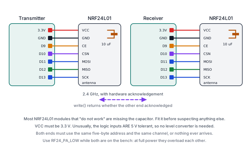
Wiring steps
Do this twice, once per board. They are wired identically.
- Unplug the USB cable.
- Find pin 1 on the module, marked with a square pad.
GNDtoGND, andVCCto the Uno’s3.3V.- Fit the 10 µF capacitor across
VCCandGND, as close to the module as you can. Stripe to ground. CEtoD9,CSNtoD10.SCKtoD13,MOSItoD11,MISOtoD12.- Plug the USB cable back in.
Keep the leads short. SPI over long loose jumpers is unreliable, and this is a radio you will later want to blame instead.
Software and libraries
Install RF24 by TMRh20 through Library Manager. Record the version; the interface has changed across major versions.
Minimal working example
Prove the module is alive before trying to send anything.
// Siratek: is the radio actually there? Run this on both boards first.

#include <SPI.h>
#include <RF24.h>

RF24 radio(9, 10);        // CE, CSN

void setup() {
  Serial.begin(9600);
  while (!Serial) {
    ;
  }

  if (!radio.begin()) {
    Serial.println("Siratek: radio not responding.");
    Serial.println("  Check VCC is 3.3V, check CE and CSN, check the SPI wiring.");
    while (1) {
      delay(100);
    }
  }

  Serial.println("Siratek: radio found.");
  radio.printDetails();   // dumps the registers; all zeros or all ones means wiring
}

void loop() {
}
printDetails() earns its place. A module that is not talking at all prints registers that are all 0x00 or all 0xFF, which tells you immediately that the problem is SPI wiring rather than anything to do with radio. Sensible-looking values mean the module is there and you can move on.
Transmitter
// Siratek: the sending board.

#include <SPI.h>
#include <RF24.h>

RF24 radio(9, 10);

// Both boards must use this same address.
const byte address[6] = "SIRA1";

struct Packet {
  uint16_t count;
  int16_t  temperatureTenths;
};

Packet packet = {0, 0};

void setup() {
  Serial.begin(9600);
  radio.begin();

  radio.openWritingPipe(address);
  radio.setPALevel(RF24_PA_LOW);     // low power while both are on the bench
  radio.stopListening();

  Serial.println("Siratek: transmitting.");
}

void loop() {
  packet.count++;
  packet.temperatureTenths = 243;    // 24.3 C, as tenths, to avoid floats

  bool ok = radio.write(&packet, sizeof(packet));

  Serial.print("sent ");
  Serial.print(packet.count);
  Serial.println(ok ? ": acknowledged" : ": no acknowledgement");

  delay(1000);
}
write() returns whether the other end acknowledged. The radio does that handshake in hardware, so this one boolean tells you whether the packet arrived, with no code at the far end. It is the most useful diagnostic this part offers.
RF24_PA_LOW while testing. At full power two modules sitting next to each other can overload each other’s receivers, so the classic first experiment fails for a reason that has nothing to do with your wiring. Turn the power up once it works at range.
Sending a struct, not a string, keeps packets small and avoids parsing. Both sketches must declare the same struct; adding a field to one and not the other produces nonsense rather than an error.
Receiver
// Siratek: the receiving board.

#include <SPI.h>
#include <RF24.h>

RF24 radio(9, 10);

const byte address[6] = "SIRA1";

struct Packet {
  uint16_t count;
  int16_t  temperatureTenths;
};

void setup() {
  Serial.begin(9600);
  radio.begin();

  radio.openReadingPipe(0, address);
  radio.setPALevel(RF24_PA_LOW);
  radio.startListening();

  Serial.println("Siratek: listening.");
}

void loop() {
  if (!radio.available()) {
    return;
  }

  Packet packet;
  radio.read(&packet, sizeof(packet));

  Serial.print("packet ");
  Serial.print(packet.count);
  Serial.print("  temperature ");
  Serial.print(packet.temperatureTenths / 10.0, 1);
  Serial.println(" C");
}
Note the count field. Watching it arrive as 1, 2, 3, 5, 6 tells you packet 4 was lost, which is information a bare reading cannot give you. Any radio link should carry a sequence number for exactly this reason.
Range, and what affects it
The bare-PCB-antenna modules in this kit manage perhaps twenty to thirty metres indoors with walls, more outdoors in the open. The versions with an external antenna and a power amplifier do considerably better and need a more generous supply still.
What hurts: metal near the antenna, a module lying flat on a metal surface, walls at an angle, and 2.4 GHz Wi-Fi on a nearby channel. Standing the module upright and away from the board helps more than you would expect.
Expected result
Both boards printing “radio found” and sensible register values. Then a packet a second, with “acknowledged” on the transmitter and an increasing count on the receiver.
Walk away with the receiver and watch where the acknowledgements stop. That is your real range, and it is the only figure that matters.
Troubleshooting
| Symptom | Likely cause | Check or fix |
|---|---|---|
| Works at 30 cm, fails further away | No capacitor | Fit 10 µF across VCC and GND |
| Transmits nothing at all | Same cause, more often than not | Fit the capacitor first |
printDetails() all zeros or all ones |
SPI wiring | Check MOSI, MISO, SCK, CSN |
begin() fails |
Power or wiring | VCC must be 3.3 V |
| Module dead after one use | 5 V on VCC |
That pin is 3.3 V only |
| Initialises, nothing arrives | Addresses differ | Both ends, byte for byte |
| Initialises, still nothing | CE and CSN swapped |
They do different jobs |
| Nonsense values received | Structs differ between sketches | Keep them identical |
| Fails with both on the bench | Receiver overloaded at full power | Use RF24_PA_LOW |
| Intermittent at any distance | Long jumper leads, or metal nearby | Shorten; stand the module up |
| Packet numbers skip | Genuine packet loss | Normal at range; the count shows it |
Next steps
- Easier first: Mixing 3.3 V and 5 V Safely, though this part needs it only on
VCC. - Related: Sending Sensor Data with MQTT, when the data has to reach a network rather than another Arduino.
- Next project: a remote sensor in a shed reporting to a display indoors, with a sequence number so you can see what is lost.
Sources and attribution
All text, wiring guidance and code in this tutorial are original Siratek work.
- nRF24L01+ datasheet for the supply range, the 5 V tolerant inputs, the current drawn during transmission and the automatic acknowledgement behaviour.
- RF24 library documentation for the calls used.
- The PCB-trace antenna, the 16 MHz crystal and the two-by-four header were read from the Siratek product photographs for item 2627.
Range figures are typical for a PCB-antenna module and depend heavily on surroundings; the tutorial gives a procedure for measuring your own. No third-party tutorial text, diagrams, photographs or code has been reproduced here.