

01
Nov
Smoke and Gas Sensing with MQ-2
Draft. This tutorial has not been checked against the physical product yet. Confirm wiring, pin assignments and voltage limits against the product documentation before building it.
| Difficulty | Advanced |
|---|---|
| Category | Sensors |
| Supported boards | Arduino Uno R3 and compatible ATmega328P boards |
| Time needed | 60 minutes |
| Prerequisites | Measuring Light with an LDR |
| Tested board | Not yet verified |
| Tested on | Not yet verified |
| Arduino IDE version | Not yet verified |
| Library | Not yet verified |
What it does
Inside the steel mesh cap is a small bead of tin dioxide and a heater. Heated to a few hundred degrees, the bead’s surface resistance changes when certain gases touch it: LPG, propane, butane, methane, hydrogen, alcohol vapour and smoke among them. The board turns that resistance into a voltage you can read.
It is the most capable sensor in this batch and the one with the most ways to mislead you. Three things have to be said before any code, because a tutorial that leaves them out produces a project its owner trusts more than they should.
Read this before you build anything with it
It is not calibrated, and it cannot be made calibrated here. The reading tells you the level has gone up or down. Turning that into parts per million requires calibrating against a known concentration of a known gas in controlled conditions, which needs equipment you do not have on a bench. Any sketch that prints “ppm” from this module alone is printing a number with no basis. Treat the output as a trend, and nothing more.
It cannot tell you which gas it is. One bead responds to a whole family of gases with different sensitivities. A rise could be LPG from a cylinder, alcohol from a cleaning cloth, or smoke from cooking. The sensor has no way to distinguish them and neither do you.
It is not a substitute for a certified gas alarm. A real detector is tested, approved, powered independently, and designed to fail safely and audibly. This module is a learning component: it needs a working Arduino, it drifts with temperature and humidity, and it reports nothing at all if the sketch crashes. LPG cylinders are common in Ghanaian kitchens and a leak is genuinely dangerous. Build this project for the understanding. Buy a certified detector for the kitchen.
With that established, it is an excellent sensor to learn on, and the techniques below are the honest way to use it.
Before you begin
Required parts and tools
- An Arduino Uno or compatible board.
- One MQ-2 module. This is Siratek product 2949.
- Four jumper wires.
- Patience, for the burn-in described below.
What is on the board
The Siratek part is the small blue MH MQ Sensor board: the sensor can, an LM393 comparator, a blue trimmer, POWER LED and DOUT LED indicators, and a four-pin header labelled
AO DO GND VCC
Note that order, and note that it differs from the sound sensor’s. Read the silkscreen rather than copying a layout from another board.
The heater, and the current it takes
The heater runs continuously and draws roughly 150 milliamps at 5 V. Two consequences.
The sensor gets hot. Warm to the touch, sometimes uncomfortably so, within a minute of powering up. That is the sensor working, not a fault.
It eats your current budget. On USB you have perhaps 450 milliamps for everything beyond the board itself, so this one module takes a third of it. Add a display and a couple of other sensors and you are at the edge. See Powering Your Project.
It also means this sensor cannot be switched on only when needed, the way the soil probe can. It needs minutes of heating before a reading means anything.
Two kinds of warming up
Preheat, every time you power it on: two to three minutes. Readings before that are high and falling and mean nothing. Build the wait into your sketch rather than hoping to remember it.
Burn-in, once in the sensor’s life: 24 to 48 hours of continuous power. A brand new sensor drifts considerably over its first day or two as the bead settles. Thresholds chosen before burn-in will be wrong afterwards.
This is the step people skip, and it is why a project that worked on Monday reports nonsense on Tuesday. Leave the board powered on a shelf for a day or two before you set any threshold.
Where to put it
LPG, propane and butane are heavier than air and collect low down. Methane and natural gas are lighter than air and collect at the ceiling. A sensor at the wrong height for the gas you care about may never see a leak.
For LPG, mount it low, around thirty centimetres from the floor. Keep it out of draughts and away from the cooker itself, where cooking fumes will trigger it constantly.
One tutorial for the whole family
Siratek also stocks MQ-3 for alcohol, MQ-4 for methane, MQ-5 for LPG and natural gas, MQ-7 for carbon monoxide and MQ-135 for air quality. They all work exactly the same way: same board, same pins, same heater, same burn-in, same honest limits. What changes is the bead chemistry and therefore which gases it responds to.
Everything in this tutorial applies to all of them. The MQ-7 is the one exception worth flagging: carbon monoxide detection properly requires cycling the heater between two voltages, which is beyond what this board does on its own.
Pin reference
| Pin or label | Connect to | Purpose | Notes |
|---|---|---|---|
AO |
Uno A0 |
Analog level | The one to use |
DO |
Uno D2, optional |
Threshold output | Set by the trimmer |
GND |
Uno GND |
Ground | |
VCC |
Uno 5V |
Power and heater | Around 150 mA, continuously |
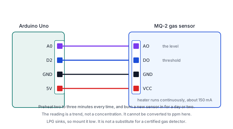
Wiring steps
- Unplug the USB cable.
GNDtoGND.VCCto5V.AOtoA0.DOtoD2, if you want the comparator output as well.- Plug the USB cable back in. The power LED lights and the can starts to warm.
- If this sensor has never been burnt in, leave it powered for a day before trusting anything.
Software and libraries
No library is required, and this is deliberate. Libraries exist that convert MQ readings into parts per million using curves from the datasheet. Those curves assume a calibrated sensor in known conditions, so on an uncalibrated bench module they produce a confident-looking number that is not a measurement.
Read the raw value. It is more honest and, for detecting a change, just as useful.
Minimal working example
// Siratek: MQ-2 raw level, with the preheat built in.

const int gasPin = A0;
const unsigned long preheatMs = 180000UL;   // three minutes

void setup() {
  Serial.begin(9600);
  Serial.println("Siratek: preheating for three minutes.");

  unsigned long start = millis();
  while (millis() - start < preheatMs) {
    Serial.print("  warming, raw = ");
    Serial.println(analogRead(gasPin));
    delay(10000);
  }

  Serial.println("ready. Baseline readings follow.");
}

void loop() {
  Serial.print("raw = ");
  Serial.println(analogRead(gasPin));
  delay(1000);
}
Printing during the preheat is worth the lines. You can watch the value fall and level off, which teaches more about this sensor than any amount of prose, and it tells you when three minutes is actually enough for your part.
Once it has settled, note the resting value in clean air. That is your baseline, and it is the only number that means anything.
Detecting a change from the baseline
A fixed threshold goes wrong as the day warms up or the humidity changes. Measuring against a slowly updated baseline is far more robust.
// Siratek: alarm on a rise above a slowly drifting baseline.

const int gasPin = A0;
const int buzzerPin = 8;

// How far above the baseline counts as an event. Measure your own.
const int riseThreshold = 120;

// The baseline follows slow changes and ignores fast ones.
float baseline = 0;
const float smoothing = 0.995;

bool alarming = false;

void setup() {
  pinMode(buzzerPin, OUTPUT);
  Serial.begin(9600);

  Serial.println("Siratek: preheating.");
  delay(180000);

  baseline = analogRead(gasPin);
  Serial.print("baseline = ");
  Serial.println(baseline);
}

void loop() {
  int raw = analogRead(gasPin);
  int rise = raw - (int) baseline;

  if (!alarming && rise > riseThreshold) {
    alarming = true;
    digitalWrite(buzzerPin, HIGH);
    Serial.println("RISE DETECTED");
  } else if (alarming && rise < riseThreshold / 2) {
    alarming = false;
    digitalWrite(buzzerPin, LOW);
    Serial.println("clear");
  }

  // Only let the baseline drift while nothing is happening,
  // or a slow leak would quietly become the new normal.
  if (!alarming) {
    baseline = smoothing * baseline + (1.0 - smoothing) * raw;
  }

  Serial.print("raw = ");
  Serial.print(raw);
  Serial.print("  baseline = ");
  Serial.print((int) baseline);
  Serial.print("  rise = ");
  Serial.println(rise);

  delay(500);
}
Two deliberate choices here.
The baseline is frozen while the alarm is active. Otherwise a gradual leak would be absorbed into the baseline and the alarm would clear itself, which is the worst possible failure for this kind of sketch.
The clear threshold is half the trigger threshold. The hysteresis from the LDR and relay tutorials, applied again.
Testing it safely
Do not open a gas cylinder to test this.
A cotton bud dipped in alcohol hand sanitiser, held near the mesh, produces a large and obvious rise with no hazard at all. A smouldering match blown out nearby works for the smoke response. Both give you a clear signal and neither fills the room with anything you would rather not have there.
Expected result
A high reading at power-up, falling over two or three minutes to a steady baseline. Then a sharp rise when something the sensor responds to comes near, and a slow return afterwards.
The recovery is slow, often tens of seconds. The bead has to clear, and that lag is a property of the sensor rather than a fault.
Troubleshooting
| Symptom | Likely cause | Check or fix |
|---|---|---|
| Module gets hot | The heater is working | Normal for every MQ sensor |
| Reading very high at first | Still preheating | Wait two to three minutes |
| Readings drift for a day or two | Never burnt in | Leave it powered 24 to 48 hours, once |
| Threshold that worked now does not | Temperature or humidity changed | Compare against a drifting baseline |
| Triggers while cooking | It responds to many gases | Move it away from the cooker |
| Never triggers on a real leak | Mounted at the wrong height | LPG sinks; mount low |
| Board resets when it is connected | 150 mA on top of everything else | Check the current budget |
DO always or never active |
Trimmer position | Set it against measured AO values |
| Want a reading in ppm | Not possible without calibration | Use the raw trend |
| Slow to return to baseline | The bead clearing | Expected; tens of seconds |
| Relying on it as a gas alarm | It is not one | Fit a certified detector as well |
Next steps
- Easier first: Measuring Light with an LDR, for the analog reading and threshold pattern.
- Related products: MQ-3, MQ-4, MQ-5, MQ-7 and MQ-135, all of which this tutorial covers.
- Next project: a gas leak alarm with a buzzer and an indicator, built and sited as a learning exercise alongside a proper detector.
Sources and attribution
All text, wiring guidance and code in this tutorial are original Siratek work.
- MQ-2 datasheet for the target gases, the heater supply and the preheat and burn-in guidance.
- The
MH MQ Sensorboard layout described here, anAO DO GND VCCheader with an LM393, a trimmer andPOWER LEDandDOUT LEDindicators, was read from the Siratek product photographs for item 2949.
Heater current and warm-up times are typical figures that vary between parts. This tutorial deliberately does not convert readings into parts per million, because an uncalibrated module cannot support that claim, and it states plainly that the module is not a substitute for a certified gas detector. No third-party tutorial text, diagrams, photographs or code has been reproduced here.