

01
Nov
An 8×8 Dot Matrix with MAX7219
Draft. This tutorial has not been checked against the physical product yet. Confirm wiring, pin assignments and voltage limits against the product documentation before building it.
| Difficulty | Intermediate |
|---|---|
| Category | Displays |
| Supported boards | Arduino Uno R3 and compatible ATmega328P boards |
| Time needed | 55 minutes |
| Prerequisites | Driving a 4-Digit 7-Segment Display |
| Tested board | Not yet verified |
| Tested on | Not yet verified |
| Arduino IDE version | Not yet verified |
| Library | Not yet verified |
What it does
Sixty-four LEDs in an eight by eight grid, driven by a MAX7219, which is a chip built to do exactly the multiplexing you did by hand on the seven-segment display.
The difference is what it frees you from. The MAX7219 holds the whole image in its own memory and refreshes the matrix continuously, by itself, forever. Your sketch sends an update when something changes and then goes back to whatever else it was doing. No timing, no refresh loop, no flicker when the rest of your code is busy.
It also handles current limiting for all sixty-four LEDs with one resistor, which is already fitted on the module, and offers sixteen brightness levels in software.
Before you begin
Required parts and tools
- An Arduino Uno or compatible board.
- One MAX7219 8×8 dot matrix module. This is Siratek product 2478.
- Five female-to-male jumper wires. The Siratek part is supplied with a five-way lead.
What is on the board
A green PCB carrying a MAX7219CNG in a 24-pin DIP socket area, an 8×8 red matrix, and two five-pin headers, one on each edge:
- The input header:
VCC,GND,DIN,CS,CLK. - The output header on the opposite edge:
VCC,GND,DOUT,CS,CLK.
That second header is for chaining. DOUT of one module goes to DIN of the next, and the clock and chip-select lines are shared, so several modules make a long scrolling display on the same three Arduino pins.
Check which header you are plugged into. They look identical, and a module wired by its output header does nothing.
Current, which is the one thing to respect
All sixty-four LEDs lit at full brightness is a lot of current. The MAX7219 limits it through the onboard resistor, but a full-brightness module can still draw a few hundred milliamps.
On USB power with one module, at a sensible brightness, this is fine. Beyond that:
- Set the brightness down in software.
setIntensity(0)is the lowest of sixteen levels and is perfectly readable indoors. There is rarely a reason to run at 15. - Two or more modules want their own 5 V supply, with the grounds joined, exactly as in Powering Your Project.
A board that resets when the display fills with lit pixels is telling you about current, not code.
It is not I2C
DIN, CS and CLK are an SPI-style arrangement: data, chip select and clock. It is not the two-wire I2C bus, and it does not share pins with an I2C display.
You can use any three digital pins, because the library bit-bangs the protocol rather than using the hardware SPI peripheral. That is slower than hardware SPI and entirely fast enough here.
Pin reference
| Module pin | Connect to | Purpose | Notes |
|---|---|---|---|
VCC |
Uno 5V |
Power | Own supply for more than one module |
GND |
Uno GND |
Ground | |
DIN |
Uno D11 |
Data in | On the input header |
CS |
Uno D10 |
Chip select | Also called LOAD |
CLK |
Uno D13 |
Clock |
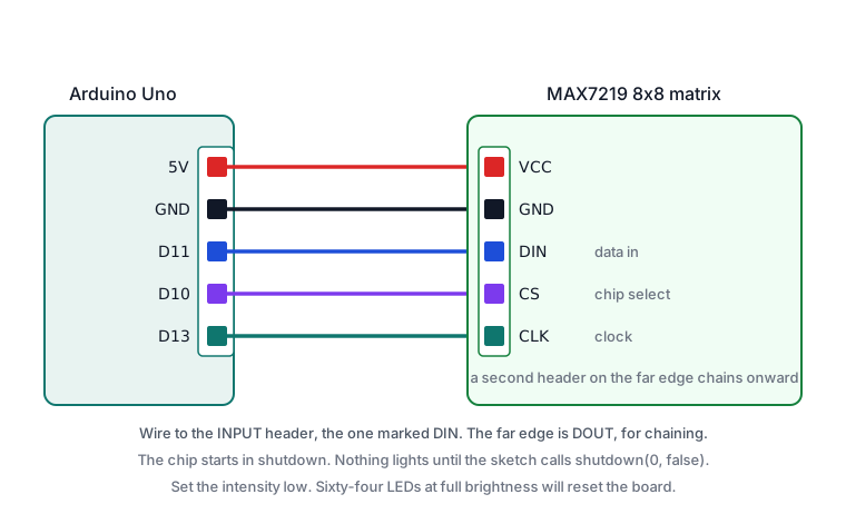
Wiring steps
- Unplug the USB cable.
- Identify the input header, the one with
DINrather thanDOUT. GNDtoGND,VCCto5V.DINtoD11,CStoD10,CLKtoD13.- Plug the USB cable back in. Nothing will light until a sketch starts the chip, which is normal.
Software and libraries
Install LedControl through Library Manager. It is small, it does one thing, and it matches the way this chip actually works, which makes it a good first library for this part.
For scrolling text across several chained modules, MD_MAX72XX with MD_Parola is the usual choice and is considerably more capable. Start with LedControl.
Minimal working example
// Siratek: a single 8x8 matrix on a MAX7219.

#include <LedControl.h>

// DIN, CLK, CS, and the number of chained modules.
LedControl matrix = LedControl(11, 13, 10, 1);

void setup() {
  // The chip powers up in shutdown. Nothing works until this.
  matrix.shutdown(0, false);

  matrix.setIntensity(0, 2);   // 0 to 15. Low is plenty indoors.
  matrix.clearDisplay(0);
}

void loop() {
  // A dot walking across the whole grid.
  for (int row = 0; row < 8; row++) {
    for (int col = 0; col < 8; col++) {
      matrix.setLed(0, row, col, true);
      delay(40);
      matrix.setLed(0, row, col, false);
    }
  }
}
The shutdown(0, false) line is the one everybody misses. The MAX7219 starts in a low-power shutdown mode, and a sketch that skips this call leaves the display dark with no error and no clue. If your matrix does nothing, check this before checking the wiring.
The first argument to every call is the device number, counting from zero. With one module it is always 0.
Drawing a shape
// Siratek: a whole image at once, one row per byte.

#include <LedControl.h>

LedControl matrix = LedControl(11, 13, 10, 1);

const byte smile[8] = {
  0b00111100,
  0b01000010,
  0b10100101,
  0b10000001,
  0b10100101,
  0b10011001,
  0b01000010,
  0b00111100
};

void draw(const byte image[8]) {
  for (int row = 0; row < 8; row++) {
    matrix.setRow(0, row, image[row]);
  }
}

void setup() {
  matrix.shutdown(0, false);
  matrix.setIntensity(0, 2);
  matrix.clearDisplay(0);
  draw(smile);
}

void loop() {
}
Writing the image in binary like this means the source code looks like the picture, which makes designing a shape a matter of typing rather than arithmetic.
Note that loop() is empty and the face stays on the display indefinitely. That is the whole advantage over hand multiplexing: the chip is doing the refreshing, and your sketch is free.
If the image comes out rotated or mirrored
It very often does. The matrix can be mounted on the PCB in any of four orientations, and manufacturers are not consistent, so setRow() may run down the display, across it, or backwards.
Rather than guessing, find out. Light a single corner and look:
matrix.setLed(0, 0, 0, true);Wherever that dot appears is row 0, column 0. If it is not the corner you expected, rotate your image array to suit, or swap setRow() for setColumn(). Both are one-line changes and neither is a fault.
Chaining modules
// Four modules on the same three pins.
LedControl matrix = LedControl(11, 13, 10, 4);

void setup() {
  for (int device = 0; device < 4; device++) {
    matrix.shutdown(device, false);
    matrix.setIntensity(device, 2);
    matrix.clearDisplay(device);
  }
}
Each module needs setting up individually, which is what the loop is for. Wire DOUT of the first to DIN of the second, share CLK and CS, and give four modules their own supply.
Expected result
A dot walking across all sixty-four positions with the first sketch, or a steady face with the second, with no flicker and no attention from your code.
At intensity 2 the display should be comfortably readable in a lit room. If you find yourself reaching for 15, something else is wrong, usually the viewing angle.
Troubleshooting
| Symptom | Likely cause | Check or fix |
|---|---|---|
| Display completely dark | shutdown(0, false) not called |
The chip starts in shutdown |
| Dark, and that call is there | Wired to the output header | Use the header with DIN |
| Nothing, no power | VCC or GND |
Check both first |
| Image rotated or mirrored | Matrix mounted differently | Light one corner and adapt |
| Board resets when many LEDs light | Current draw | Lower the intensity, or a separate supply |
| Flickers with more than one module | Supply sagging | Own supply, grounds joined |
| Only the first module works | DOUT to DIN not wired |
Check the chain, and the device count |
| Random pixels lit | Loose CLK or CS |
Reseat; keep the leads short |
| Too bright to look at | Intensity set high | 1 or 2 is usually right |
Expecting it on A4 and A5 |
This is not I2C | Any three digital pins |
Next steps
- Easier first: Driving a 4-Digit 7-Segment Display, to see what this chip is doing for you.
- Related: A 0.96 inch OLED Display, when you need text rather than pixels.
- Next project: chain four modules and scroll a message, using MD_Parola.
Sources and attribution
All text, wiring guidance and code in this tutorial are original Siratek work.
- MAX7219 datasheet for the shutdown-on-power-up behaviour, the intensity control and the single current-setting resistor.
- LedControl library documentation for the calls used.
- The
MAX7219CNGmarking, the two five-pin headers and the supplied five-way lead were read from the Siratek product photographs for item 2478.
Matrix orientation varies between modules, so this tutorial gives a one-line test rather than asserting a fixed mapping. Current figures are typical and depend on the intensity setting and how many LEDs are lit. No third-party tutorial text, diagrams, photographs or code has been reproduced here.