

01
Nov
Wiring a 16×2 LCD Directly
Draft. This tutorial has not been checked against the physical product yet. Confirm wiring, pin assignments and voltage limits against the product documentation before building it.
| Difficulty | Intermediate |
|---|---|
| Category | Displays |
| Supported boards | Arduino Uno R3 and compatible ATmega328P boards |
| Time needed | 60 minutes |
| Prerequisites | A 16x2 LCD over I2C |
| Tested board | Not yet verified |
| Tested on | Not yet verified |
| Arduino IDE version | Not yet verified |
| Library | Not yet verified |
What it does
This is the same 16×2 character display as the I2C one, without the backpack. Sixteen pins, wired by hand, driven by the LiquidCrystal library that already ships with the Arduino IDE.
It is more work, and it is worth doing once. The backpack version hides what a character LCD actually needs, and when it misbehaves you have no way to look inside. Wire one directly and the whole arrangement stops being magic: you can see the data lines, the register-select line, the enable pulse and the contrast divider, and from then on the I2C version is just those same signals with a chip in front of them.
If you only want a working display in a project, buy the backpack version, Siratek 2484, and read A 16×2 LCD over I2C instead.
Before you begin
Required parts and tools
- An Arduino Uno or compatible board.
- One 16×2 LCD without a backpack. This is Siratek product 5685.
- One 10 kilohm potentiometer, for contrast.
- One 220 ohm resistor, for the backlight.
- A breadboard and about sixteen jumper wires.
- A soldering iron, if your panel came without its header strip fitted.
That last one surprises people. Many 1602 panels ship with a loose sixteen-pin header that has to be soldered on before anything can be plugged in. Check yours before setting aside an evening.
Six pins, not eight
The display has eight data lines, D0 to D7. You will use only four of them.
The HD44780 controller inside accepts a byte either as one eight-bit transfer or as two four-bit halves. The four-bit mode is slightly slower and saves four Arduino pins, and for text on a character display the speed difference is invisible. Every tutorial, including this one, uses four bits. D0 to D3 are left unconnected.
So the real cost is six pins: RS, E, and D4 to D7. On an Uno that is still a third of your digital pins gone to one display.
The sixteen pins, and what they do
Numbered from the end marked 1 on the silkscreen:
| Pin | Name | What it is for |
|---|---|---|
| 1 | VSS |
Ground |
| 2 | VDD |
5 V |
| 3 | V0 |
Contrast. This is an input, and it needs a voltage, not a connection |
| 4 | RS |
Register select: is this byte a character or a command? |
| 5 | RW |
Read or write. Tie to ground, meaning write only |
| 6 | E |
Enable. The pulse that tells the display to take the byte |
| 7 to 10 | D0 to D3 |
Unused in four-bit mode |
| 11 to 14 | D4 to D7 |
The four data lines |
| 15 | A |
Backlight anode |
| 16 | K |
Backlight cathode |
Two of those deserve more than a table row.
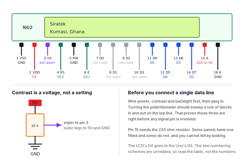
Pin 3, V0. Contrast is not a setting in software. It is an analog voltage on this pin, and the display is only readable within a narrow part of its range. That is what the potentiometer is for: it forms a divider between 5 V and ground, and its wiper feeds V0. Connect V0 straight to ground or leave it floating and you get a blank screen or a row of solid blocks, which is the same symptom the backpack version produces when its trimmer is wrong.
Pin 15, A. The backlight is an LED, and like any LED it needs current limiting. The 220 ohm resistor goes in this line. Some panels have a resistor fitted on the board already and some do not, and there is no reliable way to tell by looking. Fitting the resistor when one is already present costs you a little brightness. Leaving it out when one is not present shortens the backlight’s life, and on some panels ends it quickly.
Fit the resistor.
Pin reference
| LCD pin | Connect to | Purpose |
|---|---|---|
1 VSS |
Uno GND |
Ground |
2 VDD |
Uno 5V |
Power |
3 V0 |
Potentiometer wiper | Contrast voltage |
4 RS |
Uno D12 |
Register select |
5 RW |
Uno GND |
Write only |
6 E |
Uno D11 |
Enable |
11 D4 |
Uno D5 |
Data |
12 D5 |
Uno D4 |
Data |
13 D6 |
Uno D3 |
Data |
14 D7 |
Uno D2 |
Data |
15 A |
Uno 5V through 220 ohms |
Backlight |
16 K |
Uno GND |
Backlight |
The potentiometer’s two outer legs go to 5V and GND; the middle leg goes to V0.
Note that the LCD’s D4 goes to the Uno’s D5, not its D4. The two numbering schemes are unrelated, and reading the table rather than pattern-matching the numbers will save you an hour.
Wiring steps
Do this in four groups rather than pin by pin. Wiring sixteen connections in one pass and then hunting for the one that is wrong is miserable.
- Unplug the USB cable.
- Power first. Pin 1 to
GND, pin 2 to5V, pin 5 toGND. - Contrast next. Potentiometer outer legs to
5VandGND, wiper to pin 3. - Backlight. Pin 15 through the 220 ohm resistor to
5V, pin 16 toGND. - Plug in the USB cable. The backlight should light, and turning the potentiometer should sweep a row of blocks in and out of view on the top line. That is your proof that power and contrast are right, before a single data line is connected. Do not continue until you have seen it.
- Unplug again.
- Control lines. Pin 4 to
D12, pin 6 toD11. - Data lines. Pin 11 to
D5, pin 12 toD4, pin 13 toD3, pin 14 toD2. - Plug the USB cable back in.
Step 5 is the one that makes this tutorial easier than it looks. It splits the job into two halves that fail in different ways.
Software and libraries
No installation needed. LiquidCrystal is part of the Arduino IDE.
This is the opposite of the I2C version, which needs a third-party library and cannot use this one.
Minimal working example
// Siratek: a 16x2 LCD wired directly, in four-bit mode.

#include <LiquidCrystal.h>

// The order is RS, E, D4, D5, D6, D7, as Arduino pin numbers.
LiquidCrystal lcd(12, 11, 5, 4, 3, 2);

void setup() {
  lcd.begin(16, 2);

  lcd.setCursor(0, 0);
  lcd.print("Siratek");
  lcd.setCursor(0, 1);
  lcd.print("Kumasi, Ghana");
}

void loop() {
}
The constructor’s argument order is RS, E, D4, D5, D6, D7. Get it wrong and the display shows nothing, or nonsense, with no other clue. It is the first thing to check when a directly wired LCD misbehaves.
Seeing the enable pulse
Here is something the I2C version cannot show you. Slow the display down until you can watch it work.
// Siratek: writing one character at a time, slowly enough to watch.

#include <LiquidCrystal.h>

LiquidCrystal lcd(12, 11, 5, 4, 3, 2);

const char message[] = "Siratek Kumasi";

void setup() {
  lcd.begin(16, 2);
}

void loop() {
  lcd.clear();

  for (int i = 0; message[i] != '\0'; i++) {
    lcd.setCursor(i, 0);
    lcd.print(message[i]);
    delay(200);
  }

  delay(1500);
}
Each character here is two four-bit transfers and two enable pulses. The library is doing exactly what the backpack’s chip does, on pins you can reach with a multimeter probe.
Expected result
Backlight on as soon as power is connected. A row of blocks sweeping in and out as the potentiometer turns, before any code. Two lines of text after upload, with the contrast set so the blocks behind the characters have just disappeared.
Troubleshooting
| Symptom | Likely cause | Check or fix |
|---|---|---|
| Blank screen, backlight on | Contrast | Turn the potentiometer through its full range |
| Solid blocks, no text | Contrast too high, or data lines wrong | Adjust first, then check pins 11 to 14 |
| No blocks at any contrast setting | V0 not fed, or VSS and VDD swapped |
Check the divider and power before anything else |
| Nothing at all, no backlight | Backlight not wired, or resistor open | Check pins 15 and 16 |
| Garbled or random characters | Constructor argument order | It is RS, E, D4, D5, D6, D7 |
| First character right, rest wrong | One data line loose | Reseat pins 11 to 14 |
| Text appears then freezes | RW floating |
Tie pin 5 to GND |
| Works, then fails when touched | Header not soldered, or a loose jumper | Solder the header; reseat the wires |
| Display works but the board resets | Backlight current with no resistor | Fit the 220 ohm resistor in pin 15 |
| Out of pins for the rest of the project | Six pins is the real cost | Use the I2C version, Siratek 2484 |
Next steps
- Easier first: A 16×2 LCD over I2C, which is this display with the wiring done for you.
- Related: More Outputs with a Shift Register, the other answer to running out of pins.
- Next project: now that you have seen the signals, the backpack version will make sense as a convenience rather than a black box.
Sources and attribution
All text, wiring guidance and code in this tutorial are original Siratek work.
- Arduino core documentation for the
LiquidCrystallibrary. - Pin numbering and function follow the standard HD44780-compatible 1602 arrangement.
Whether a backlight resistor is fitted on the panel varies between batches, so this tutorial fits one rather than assuming either way. No third-party tutorial text, diagrams, photographs or code has been reproduced here.