

01
Nov
Running an ATmega328P Without the Board
Draft. This tutorial has not been checked against the physical product yet. Confirm wiring, pin assignments and voltage limits against the product documentation before building it.
| Difficulty | Advanced |
|---|---|
| Category | Foundations |
| Supported boards | Bare ATmega328P, programmed from an Arduino Uno |
| Time needed | 75 minutes |
| Prerequisites | Regulators, Batteries and Solar |
| Tested board | Not yet verified |
| Tested on | Not yet verified |
| Arduino IDE version | Not yet verified |
| Library | Not yet verified |
What it does
Take the chip out of the Uno, put it on a breadboard with two or three other components, and your sketch runs exactly as before.
That is the whole idea, and it is worth doing once because of what it reveals: an Arduino Uno is a chip, a crystal, a regulator and a USB adapter. Everything else on the board is convenience. Once you have seen a sketch run on a chip and a capacitor, the board stops being magic and starts being a tool.
It is also genuinely useful. A finished project built this way costs a fraction of a board, draws a fraction of the current, and fits where an Uno will not.
Before you begin
Required parts and tools
- An Arduino Uno, to do the programming.
- One ATmega328P in a 28-pin DIP package. This is Siratek product 6689.
- A breadboard and jumper wires.
- One 0.1 microfarad capacitor, which is not optional.
- A 10 kilohm resistor.
- Optionally: a 16 MHz crystal and two 22 pF capacitors. The first build below does without them.
Does your chip have a bootloader?
This is the first question, and it decides which of two paths you take.
A chip with the Arduino bootloader accepts sketches over serial, exactly as an Uno does. Chips sold as “with Arduino bootloader” have this; a plain ATmega328P from a component supplier usually does not.
A chip without one is blank. You can still program it, using the Uno as a programmer, and you can burn a bootloader onto it so it behaves like the first kind afterwards.
Both are covered below. If you do not know which you have, assume blank and burn a bootloader; doing so to a chip that already had one is harmless.
Finding pin 1, and the pin map
There is a notch at one end and often a dot beside pin 1. With the notch to the left, pin 1 is the bottom left, and the numbers run along the bottom and back along the top.
The Arduino pin numbers you use in a sketch are not the chip’s physical pins. The ones you will need:
| Chip pin | Arduino name | Purpose |
|---|---|---|
| 1 | RESET |
Through 10 k to 5 V |
| 7 | VCC |
Power |
| 8 | GND |
Ground |
| 9, 10 | crystal | If fitted |
| 20 | AVCC |
Also power. Must be connected |
| 22 | GND |
Also ground |
| 2, 3 | D0, D1 |
Serial |
| 17, 18, 19 | D11, D12, D13 |
SPI, used for programming |
| 19 | D13 |
The LED pin |
| 23 to 28 | A0 to A5 |
Analog |
Pin 20, AVCC, catches everyone. It supplies the analog converter, and the chip behaves erratically without it. It is not optional even if you never use an analog input.
The capacitor that is not optional either
A 0.1 µF capacitor between VCC (pin 7) and GND (pin 8), as close to the chip as possible.
It supplies the small current surges the chip draws as it switches, which the supply wires are too slow to deliver. Without it the chip resets at random, misreads inputs, or simply behaves oddly in ways that look like software faults.
Every Arduino board has them fitted; on a breadboard you have to add your own. If a bare chip is unreliable, this is the first thing to check.
The internal oscillator, which saves three parts
An Uno has a 16 MHz crystal, and you can fit one. But the ATmega328P has an internal 8 MHz oscillator, and for most projects that is enough.
| Internal 8 MHz | External 16 MHz crystal | |
|---|---|---|
| Extra parts | None | Crystal and two 22 pF capacitors |
| Speed | Half | Full |
| Accuracy | About 1 percent, and it drifts with temperature | Very accurate |
| Minimum voltage | Works down to about 2.7 V | Needs 4.5 V for 16 MHz |
That last row is the one that matters for battery projects. At 16 MHz the chip needs 4.5 V or more. At 8 MHz internal it runs happily down to 2.7 V, which means two AA cells or a lithium cell with no regulator at all.
Against that, the internal oscillator is roughly one percent accurate, so serial communication can be marginal and anything timing-critical will drift. Use the crystal if you need accurate timing or full speed; use the internal oscillator for a battery sensor.
The build below uses the internal oscillator, because it is the one that shows what the minimum really is.
Pin reference
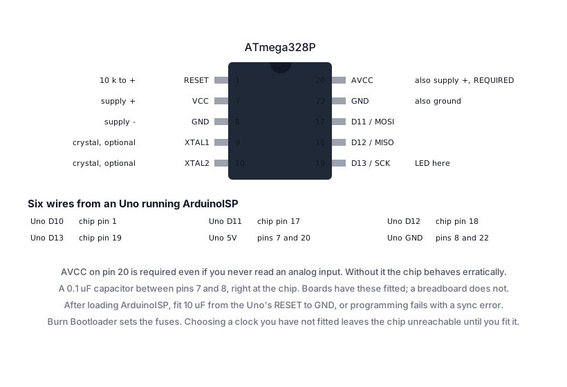
The minimum circuit, with the internal oscillator:
| Chip pin | Connect to | Purpose |
|---|---|---|
7 VCC |
Supply positive | Power |
8 GND |
Supply negative | Ground |
20 AVCC |
Supply positive | Analog supply, required |
22 GND |
Supply negative | Ground |
1 RESET |
10 k to supply positive | Held high so the chip runs |
| 7 to 8 | 0.1 µF capacitor | Decoupling, close to the chip |
Six connections and two components. That is a working microcontroller.
Wiring steps
The standalone circuit
- Seat the chip across the breadboard’s centre channel, notch to the left.
- Pin 7 and pin 20 to the positive rail. Pin 8 and pin 22 to the negative rail.
- 10 k resistor from pin 1 to the positive rail.
- 0.1 µF capacitor between pin 7 and pin 8, right at the chip.
- An LED and a 220 ohm resistor from pin 19 to ground, to see something happen.
Adding the Uno as a programmer
Six more wires, from the Uno to the chip:
| Uno | Chip pin |
|---|---|
D10 |
1, RESET |
D11 |
17 |
D12 |
18 |
D13 |
19 |
5V |
7 and 20 |
GND |
8 and 22 |
Note D10 goes to the chip’s reset, not the Uno’s.
Software and libraries
No libraries. You need one board definition added to the IDE, because “ATmega328P on its internal 8 MHz oscillator” is not a standard Arduino board.
MiniCore by MCUdude is the usual choice, added through Boards Manager with the package URL from its own documentation. It offers the ATmega328 with a choice of clock source, which is exactly what is missing otherwise.
Record the version, as always.
Doing it
1. Turn the Uno into a programmer
With nothing else connected, upload the IDE’s built-in ArduinoISP sketch to the Uno: File, Examples, ArduinoISP.
The Uno is now a programmer rather than a target. Do not upload anything else to it until you have finished.
Fit a 10 µF capacitor between the Uno’s RESET and GND after uploading ArduinoISP. It stops the Uno resetting itself when the IDE opens the port, which otherwise makes the next step fail with a confusing error. Remove it when you have finished.
2. Burn the bootloader
Wire the six programming connections, then in the IDE:
- Tools, Board: MiniCore, ATmega328
- Tools, Clock: Internal 8 MHz
- Tools, Programmer: Arduino as ISP
- Tools, Burn Bootloader
This does two things. It writes the bootloader, and more importantly it sets the fuses, which are the settings that tell the chip which clock source to use. A chip set for an external crystal with no crystal fitted will not run at all, and cannot easily be rescued without fitting one.
That is the one genuinely risky step on this page. Setting the fuses for a clock source you do not have bricks the chip until you give it that clock. Choose the clock setting deliberately, and if a chip stops responding afterwards, a crystal on pins 9 and 10 usually brings it back.
3. Upload a sketch
Two ways, and they differ:
Through the bootloader, over serial, which needs a USB-to-serial adapter wired to pins 2 and
- This is how a finished board with a bootloader is updated.
Through the ISP connection you already have, using Sketch, Upload Using Programmer. No adapter needed, and it overwrites the bootloader, which frees about half a kilobyte of flash and removes the startup delay.
For a project you will not reprogram, uploading through the programmer is the better choice.
// Siratek: proof of life on a bare chip. LED on chip pin 19.

void setup() {
  pinMode(13, OUTPUT);        // Arduino D13, which is chip pin 19
}

void loop() {
  digitalWrite(13, HIGH);
  delay(500);
  digitalWrite(13, LOW);
  delay(500);
}
If that blinks, you have a working microcontroller made of a chip, a resistor and a capacitor.
Check the timing. At 8 MHz with the board set to 8 MHz, the blink is one second. If it is two seconds, the board definition says 16 MHz and the chip is running at 8, and every delay() and every serial baud rate in your sketch is out by a factor of two. That symptom is the fastest way to catch a clock mismatch.
What this buys you
| Uno | Bare chip at 8 MHz | |
|---|---|---|
| Running current | About 50 mA | About 5 mA |
| In deep sleep | Still tens of mA | Microamps |
| Minimum supply | 7 V at the jack | 2.7 V |
| Size | A board | A chip |
The current figures are the point. An Uno cannot usefully run from batteries for long because the regulator and the USB chip draw current whatever the sketch does. A bare chip asleep between readings, directly off two AA cells, is a project that lasts months.
Troubleshooting
| Symptom | Likely cause | Check or fix |
|---|---|---|
| Nothing at all | AVCC, pin 20, not connected |
It is required even without analog |
| Random resets, odd behaviour | No decoupling capacitor | 0.1 µF at pin 7 to pin 8 |
| Will not run | RESET not pulled high |
10 k from pin 1 to positive |
| Blink is twice as slow | Clock mismatch | Board setting against the actual clock |
| Serial output is rubbish | Same cause | The baud rate scales with the clock |
| “Not in sync” when burning | Uno resetting itself | 10 µF from the Uno’s RESET to GND |
| Chip stopped responding after burning | Fuses set for a clock you do not have | Fit a 16 MHz crystal on pins 9 and 10 |
| Works on 5 V, not on 3 V | Fused for 16 MHz | 16 MHz needs 4.5 V; use internal 8 MHz |
| Sketch uploads but does nothing | Uploaded to the Uno, not the chip | Use Upload Using Programmer |
| Analog readings wrong | AVCC missing or noisy |
Connect it; add a capacitor there too |
Next steps
- Easier first: Uno, Nano, Mega, Pro Mini or ESP32, for when a bare chip is overkill.
- Related: Regulators, Batteries and Solar, because this is where that becomes worth doing.
- Next: Small Jobs on an ATtiny85, which is this idea taken further.
Sources and attribution
All text, wiring guidance and code in this tutorial are original Siratek work.
- ATmega328P datasheet for the pin assignments, the internal oscillator, the voltage and frequency relationship, and the
AVCCrequirement. - Arduino documentation for the ArduinoISP sketch and the Upload Using Programmer option.
- MiniCore documentation for the board definitions and clock options.
Siratek product 6689 is supplied as a bare DIP chip; whether an individual chip arrives with the Arduino bootloader varies, which is why this tutorial covers burning one. Current figures are typical and depend on the clock, the supply and what the sketch is doing. No third-party tutorial text, diagrams, photographs or code has been reproduced here.