

01
Nov
Reading a 4×4 Matrix Keypad
Draft. This tutorial has not been checked against the physical product yet. Confirm wiring, pin assignments and voltage limits against the product documentation before building it.
| Difficulty | Intermediate |
|---|---|
| Category | Inputs |
| Supported boards | Arduino Uno R3 and compatible ATmega328P boards |
| Time needed | 45 minutes |
| Prerequisites | Making a Button Behave |
| Tested board | Not yet verified |
| Tested on | Not yet verified |
| Arduino IDE version | Not yet verified |
| Library | Not yet verified |
What it does
Sixteen keys on a thin adhesive-backed membrane: digits 0 to 9, *, #, and A to D. It is how a project asks for a PIN, a temperature, a menu choice, anything that needs more than a button or two.
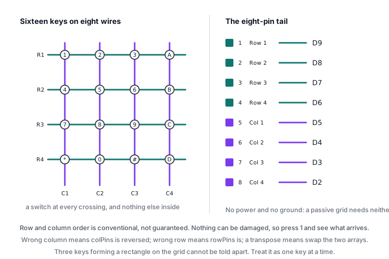
Sixteen buttons would ordinarily need sixteen pins. This needs eight, because the keys are wired as a grid: four rows crossing four columns, with a switch at each crossing. That matrix arrangement is the thing worth understanding, and it is the same idea that lets a computer keyboard put a hundred keys on far fewer wires.
Before you begin
Required parts and tools
- An Arduino Uno or compatible board.
- One 4×4 membrane keypad. This is Siratek product 5796.
- Eight female-to-male jumper wires, or a breadboard.
What you are actually holding
There are no electronics in it at all. No chip, no resistors, nothing. It is sixteen momentary switches printed on plastic film, with eight tracks running down a ribbon tail to a single row of eight male pins.
That matters because everything clever has to happen in your sketch, and because there is nothing in the keypad that can be at fault. If a key does not work, it is the connection, the pin assignment or the film itself.
Which pin is which
Eight pins in one row. With the keypad face up and the tail toward you, they are conventionally rows 1 to 4, then columns 1 to 4, left to right.
Conventionally. Some keypads reverse it, and there is no silkscreen to check.
Fortunately the cost of getting it wrong is zero: nothing can be damaged, because these are just switches. If the keys come out scrambled, the fix is to swap the two arrays in your sketch. The test sketch below is designed to make that obvious in a few seconds.
How the matrix is read
The library does this for you, but it is worth knowing, because it explains the pull-up requirement and a limitation you will eventually meet.
One column at a time is driven low while the others are left high. Each row is then read: a row that reads low must be connected to the driven column through a closed switch, which identifies exactly one key. Repeat for the four columns and you have scanned all sixteen in four steps, hundreds of times a second.
The rows need pull-up resistors so they sit high when no key is pressed, otherwise they float and read nonsense. The library uses the ATmega328P’s internal pull-ups, which is why no external resistors appear in the parts list. This is the same INPUT_PULLUP idea from Read a Push Button, applied four times.
Two keys at once
Hold two keys in the same row or column and the scan still works. Hold three that form a rectangle on the grid and the matrix cannot tell which three of the four corners are pressed, so it may report a key you are not touching. This is called ghosting.
Proper keyboards fit a diode at every key to prevent it. This keypad has none, so treat it as one key at a time. For a PIN pad or a menu that is no limitation at all.
Pin reference
| Keypad pin | Connect to | Purpose |
|---|---|---|
| 1 | Uno D9 |
Row 1 |
| 2 | Uno D8 |
Row 2 |
| 3 | Uno D7 |
Row 3 |
| 4 | Uno D6 |
Row 4 |
| 5 | Uno D5 |
Column 1 |
| 6 | Uno D4 |
Column 2 |
| 7 | Uno D3 |
Column 3 |
| 8 | Uno D2 |
Column 4 |
No power and no ground. A passive grid of switches needs neither.
Wiring steps
- Unplug the USB cable.
- Plug the eight-pin tail into a breadboard, or use female-to-male leads directly.
- Working left to right with the keypad face up, connect its pins to
D9,D8,D7,D6,D5,D4,D3,D2in that order. - Plug the USB cable back in.
Descending pin numbers look odd and keep the ribbon flat instead of crossed. Any eight digital pins work; only the sketch needs to agree with the wiring.
Software and libraries
Install Keypad by Mark Stanley and Alexander Brevig through Library Manager. It handles the scanning, the pull-ups and the debouncing.
Writing the scan by hand is a good exercise but a poor starting point, because a bug in it looks exactly like a wiring fault.
Minimal working example
// Siratek: reading a 4x4 membrane keypad.

#include <Keypad.h>

const byte ROWS = 4;
const byte COLS = 4;

char keys[ROWS][COLS] = {
  {'1', '2', '3', 'A'},
  {'4', '5', '6', 'B'},
  {'7', '8', '9', 'C'},
  {'*', '0', '#', 'D'}
};

byte rowPins[ROWS] = {9, 8, 7, 6};
byte colPins[COLS] = {5, 4, 3, 2};

Keypad pad = Keypad(makeKeymap(keys), rowPins, colPins, ROWS, COLS);

void setup() {
  Serial.begin(9600);
  Serial.println("Siratek: press keys, starting with 1.");
}

void loop() {
  char key = pad.getKey();

  if (key) {
    Serial.print("key: ");
    Serial.println(key);
  }
}
Press 1 first. If 1 appears, the wiring is right and you can stop thinking about it.
If something else appears, read what it was:
- A key from the right row but the wrong column:
colPinsis reversed. Swap it end for end. - A key from the right column but the wrong row:
rowPinsis reversed. - The transpose, so pressing
1gives1but2gives4: the keypad’s eight pins are columns-then-rows rather than rows-then-columns. Swap the two arrays.
getKey() returns 0 when nothing is pressed, which is why the if (key) guard is there. It also only reports a key once per press, not continuously, so no edge detection is needed.
Collecting a number
A single character is rarely what you want. Gathering digits until # is the standard pattern.
// Siratek: entering a number, with * to clear and # to accept.

#include <Keypad.h>

const byte ROWS = 4;
const byte COLS = 4;

char keys[ROWS][COLS] = {
  {'1', '2', '3', 'A'},
  {'4', '5', '6', 'B'},
  {'7', '8', '9', 'C'},
  {'*', '0', '#', 'D'}
};

byte rowPins[ROWS] = {9, 8, 7, 6};
byte colPins[COLS] = {5, 4, 3, 2};

Keypad pad = Keypad(makeKeymap(keys), rowPins, colPins, ROWS, COLS);

char entry[9];
byte length = 0;

void setup() {
  Serial.begin(9600);
  Serial.println("Siratek: type digits, # to accept, * to clear.");
}

void loop() {
  char key = pad.getKey();
  if (!key) {
    return;
  }

  if (key >= '0' && key <= '9') {
    if (length < sizeof(entry) - 1) {
      entry[length++] = key;
      entry[length] = '\0';
      Serial.println(entry);
    }
  } else if (key == '*') {
    length = 0;
    entry[0] = '\0';
    Serial.println("cleared");
  } else if (key == '#') {
    Serial.print("entered: ");
    Serial.println(atoi(entry));
    length = 0;
    entry[0] = '\0';
  }
}
The length check before writing into entry is not decoration. Without it, holding a key down long enough writes past the end of the array, which on an Arduino corrupts whatever variable happens to live next in memory. The symptom is a sketch that works for a minute and then behaves strangely, and it is among the hardest faults to find. Always bound the index.
On storing a PIN
If you go on to build a door lock, resist comparing against a PIN typed into the sketch as plain text. Anyone who can read the source, or dump the flash, can read the PIN.
It is beyond this page to do properly, but the shape of the answer is: store a hash of the PIN rather than the PIN, compare hashes, and accept that a hobby microcontroller is not a security device. A keypad on a drawer is fine. A keypad as the only thing between someone and your house is not.
Expected result
One line per key press, matching the key you pressed, with no repeats and no missed presses.
Membrane keys need a deliberate press. A light touch near the edge of a key often does not close the contact, and that is the membrane rather than your code.
Troubleshooting
| Symptom | Likely cause | Check or fix |
|---|---|---|
| Nothing at all | Pin order wrong in both arrays | Check the wiring against the sketch |
| Wrong column reported | colPins reversed |
Swap it end for end |
| Wrong row reported | rowPins reversed |
Same |
| Keys transposed | Keypad is columns-then-rows | Swap the two arrays |
| One row dead | A lead not seated | Reseat; the tail pins are fragile |
| One key dead, others fine | Membrane worn or creased | Nothing to repair; replace the keypad |
| Repeated characters | Not using getKey() |
getKey() already reports once per press |
| Keys need a hard press | Normal for membrane | Press squarely in the middle |
| Odd key reported with several held | Ghosting, no diodes | Use one key at a time |
| Sketch misbehaves after long input | Writing past the array | Bound the index |
Next steps
- Easier first: Making a Button Behave, for the debouncing this library hides.
- Related products: a 16×2 LCD to show what is being typed, and a relay or servo to act on it.
- Next project: an RFID door lock with a keypad as the fallback, built on a drawer rather than a front door.
Sources and attribution
All text, wiring guidance and code in this tutorial are original Siratek work.
- The sixteen-key layout and the eight-pin single-row tail were read from the Siratek product photographs for item 5796.
- Keypad library documentation for the calls used.
Row and column pin order is conventional rather than guaranteed and carries no risk of damage, so this tutorial gives a diagnostic procedure instead of asserting one. No third-party tutorial text, diagrams, photographs or code has been reproduced here.