

01
Nov
Reading Colour with a TCS3200
Draft. This tutorial has not been checked against the physical product yet. Confirm wiring, pin assignments and voltage limits against the product documentation before building it.
| Difficulty | Advanced |
|---|---|
| Category | Sensors |
| Supported boards | Arduino Uno R3 and compatible ATmega328P boards |
| Time needed | 65 minutes |
| Prerequisites | Measuring Light with an LDR |
| Tested board | Not yet verified |
| Tested on | Not yet verified |
| Arduino IDE version | Not yet verified |
| Library | Not yet verified |
What it does
An array of tiny light sensors behind coloured filters, with four white LEDs around them to illuminate whatever you point it at. Select a filter, and the chip outputs a square wave whose frequency is proportional to how much light of that colour it sees.
So reading a colour means: select red, measure the frequency, select green, measure, select blue, measure. Three numbers, and their ratios tell you the colour.
It is the only sensor in this library that reports by frequency rather than voltage, and the only one where the answer depends as much on your calibration as on the hardware.
Before you begin
Required parts and tools
- An Arduino Uno or compatible board.
- One TCS3200 colour sensor module. This is Siratek product 2874, the red
YL-64board. - Eight jumper wires.
- Something to make a hood from: black card, tape, or a 3D print.
- Samples of the colours you want to recognise, plus white and black references.
Eight pins
The board’s header is labelled:
VCC GND S0 S1 S2 S3 EO OUT
S0andS1scale the output frequency: 100 percent, 20 percent, 2 percent, or power down.S2andS3select the filter: red, green, blue or clear.EOis output enable, active low. Tie it toGND.OUTis the square wave.
Two selection tables, and they are worth having in front of you:
S0 |
S1 |
Output scaling |
|---|---|---|
| LOW | LOW | Power down |
| LOW | HIGH | 2 % |
| HIGH | LOW | 20 % |
| HIGH | HIGH | 100 % |
S2 |
S3 |
Filter |
|---|---|---|
| LOW | LOW | Red |
| LOW | HIGH | Blue |
| HIGH | LOW | Clear, no filter |
| HIGH | HIGH | Green |
Note that blue and clear are not in the order you would guess. Getting S2 and S3 the wrong way round gives readings that look plausible and are wrong, which is worse than an obvious failure.
Use 20 percent scaling on an Uno. At 100 percent the frequency can exceed what pulseIn() measures comfortably; at 2 percent each reading takes too long.
Measuring a frequency with pulseIn
pulseIn() measures how long a pulse lasts, in microseconds. A shorter pulse means a higher frequency means more light.
So the number you get is inversely related to brightness: bright red gives a small number on the red filter, not a large one. That inversion catches everyone once.
A proper frequency counter using interrupts is faster and more accurate. pulseIn() is simpler, needs no timers, and is accurate enough once calibrated, which is why it is used here.
Calibration is not optional
The raw numbers depend on the LEDs, the distance, the ambient light and the sample’s texture. There is no absolute scale.
What works is two references:
- White, which gives the smallest numbers the sensor will produce in your setup.
- Black, which gives the largest.
Everything else falls between, and map() turns a raw reading into 0 to 255 for each channel. Those three values are comparable across readings, which the raw ones are not.
Recalibrate whenever anything changes: the distance, the hood, the room lighting, or the sensor’s mounting.
The hood, which matters more than the code
Ambient light reaches the sensor and corrupts every reading. Sunlight through a window will change your results between morning and afternoon.
Build a shade so the only light the sensor sees is its own LEDs reflecting off the sample. Black card taped into a short tube is enough. Hold the sample at a fixed distance, about a centimetre, because the reading changes sharply with distance.
A sensor in free air gives numbers that wander and will not classify anything reliably. A sensor in a hood at a fixed distance is genuinely useful. The difference is cardboard, not code.
What it can and cannot do
It can tell red from green from blue from yellow, reliably, on matte samples at a fixed distance in a hood.
It cannot match paint shades, read glossy or metallic surfaces well, or work at a distance. It is a colour sorter, not a colorimeter.
Pin reference
| Module pin | Connect to | Purpose |
|---|---|---|
VCC |
Uno 5V |
Power and the four LEDs |
GND |
Uno GND |
Ground |
S0 |
Uno D4 |
Frequency scaling |
S1 |
Uno D5 |
Frequency scaling |
S2 |
Uno D6 |
Filter select |
S3 |
Uno D7 |
Filter select |
EO |
Uno GND |
Output enable, active low |
OUT |
Uno D8 |
Frequency output |
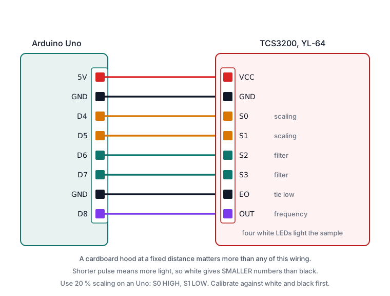
Wiring steps
- Unplug the USB cable.
GNDtoGND,VCCto5V.EOtoGND.S0toD4,S1toD5,S2toD6,S3toD7.OUTtoD8.- Plug the USB cable back in. The four white LEDs should light at once.
- Build the hood before taking any reading seriously.
Software and libraries
No library is required. pulseIn() is part of the Arduino core.
Minimal working example
// Siratek: raw readings for each filter. Smaller means more of that colour.

const int s0 = 4, s1 = 5, s2 = 6, s3 = 7, out = 8;

int readFilter(bool a, bool b) {
  digitalWrite(s2, a);
  digitalWrite(s3, b);
  delay(60);                      // let the photodiodes settle
  return pulseIn(out, LOW);
}

void setup() {
  pinMode(s0, OUTPUT);
  pinMode(s1, OUTPUT);
  pinMode(s2, OUTPUT);
  pinMode(s3, OUTPUT);
  pinMode(out, INPUT);

  // 20 % scaling: HIGH, LOW.
  digitalWrite(s0, HIGH);
  digitalWrite(s1, LOW);

  Serial.begin(9600);
  Serial.println("Siratek: hold white, then black, and write both sets down.");
}

void loop() {
  int red   = readFilter(LOW, LOW);
  int blue  = readFilter(LOW, HIGH);
  int green = readFilter(HIGH, HIGH);

  Serial.print("R ");  Serial.print(red);
  Serial.print("   G "); Serial.print(green);
  Serial.print("   B "); Serial.println(blue);

  delay(400);
}
Hold a white card at your chosen distance and write down the three numbers. Then a black one. Those six values are your calibration, and nothing works without them.
Check the direction while you are there: white should give smaller numbers than black on all three channels. If it does not, EO is probably not grounded.
Calibrated channels
// Siratek: raw readings turned into comparable 0 to 255 values.

const int s0 = 4, s1 = 5, s2 = 6, s3 = 7, out = 8;

// From the sketch above. Yours will differ, and so will mine tomorrow.
const int whiteR = 22, whiteG = 24, whiteB = 20;
const int blackR = 95, blackG = 102, blackB = 88;

int readFilter(bool a, bool b) {
  digitalWrite(s2, a);
  digitalWrite(s3, b);
  delay(60);
  return pulseIn(out, LOW);
}

int scaled(int raw, int white, int black) {
  int value = map(raw, white, black, 255, 0);
  return constrain(value, 0, 255);
}

void setup() {
  pinMode(s0, OUTPUT); pinMode(s1, OUTPUT);
  pinMode(s2, OUTPUT); pinMode(s3, OUTPUT);
  pinMode(out, INPUT);
  digitalWrite(s0, HIGH);
  digitalWrite(s1, LOW);
  Serial.begin(9600);
}

void loop() {
  int r = scaled(readFilter(LOW, LOW), whiteR, blackR);
  int g = scaled(readFilter(HIGH, HIGH), whiteG, blackG);
  int b = scaled(readFilter(LOW, HIGH), whiteB, blackB);

  Serial.print("R "); Serial.print(r);
  Serial.print("  G "); Serial.print(g);
  Serial.print("  B "); Serial.println(b);

  delay(400);
}
map() runs from white to black and 255 down to 0, which inverts the relationship so that a bigger number means more of that colour. constrain() catches samples brighter than your white reference, which otherwise produce values over 255.
Naming a colour
// Siratek: classify by which channel dominates.

const char* nameColour(int r, int g, int b) {
  int total = r + g + b;

  if (total < 120) {
    return "black or very dark";
  }
  if (r > 190 && g > 190 && b > 190) {
    return "white";
  }

  if (r > g + 40 && r > b + 40) {
    return "red";
  }
  if (g > r + 40 && g > b + 40) {
    return "green";
  }
  if (b > r + 40 && b > g + 40) {
    return "blue";
  }
  if (r > b + 50 && g > b + 50) {
    return "yellow";
  }

  return "not sure";
}
Two things make this honest.
It returns “not sure”. A classifier that always answers is a classifier that is often wrong, and in a sorting machine a confident wrong answer is worse than an admission.
The margins are generous. Forty counts between channels, not five. Tighten them and the sensor starts flipping between answers on the same sample, which is how you discover the readings are noisier than they looked.
Both the thresholds and the margins need adjusting against your own samples. Print the three values alongside the name while you tune them.
Expected result
In a hood at a fixed distance, a white card giving three roughly equal high values, a black one giving three low values, and a red sample giving a clearly dominant red channel.
Repeat a reading on the same sample five times. The three values should agree to within a few counts. If they wander by tens, light is leaking in or the distance is changing.
Troubleshooting
| Symptom | Likely cause | Check or fix |
|---|---|---|
pulseIn() returns 0 |
EO not grounded, or OUT on the wrong pin |
Check both |
| All three channels identical | S2 and S3 not switching |
Check those two wires |
| Blue and clear behave oddly | Filter table order | Blue is LOW HIGH, clear is HIGH LOW |
| White reads higher than black | Reading direction | Shorter pulse means more light |
| Readings change through the day | Ambient light | Build the hood |
| Readings change with distance | Expected | Fix the distance mechanically |
| Values over 255 | Sample brighter than the white reference | constrain(), then recalibrate |
| Classifier flips on one sample | Margins too tight | Widen them; print the raw values |
| Glossy samples read wrongly | Specular reflection | Matte samples only |
| Readings slow | 60 ms settle per channel | Three channels means about 200 ms |
| Numbers very large at 100 % scaling | pulseIn() out of its comfortable range |
Use 20 %: S0 HIGH, S1 LOW |
Next steps
- Easier first: Measuring Light with an LDR, for light without colour.
- Related products: an SG90 servo to sort what you have identified, and an LCD to name it.
- Next project: a colour sorter that drops counters into bins, which is this sensor, a servo and a lot of patient calibration.
Sources and attribution
All text, wiring guidance and code in this tutorial are original Siratek work.
- TCS3200 datasheet for the
S0toS3selection tables, the output scaling options and the frequency output behaviour. - The
YL-64board marking, the eight-pinVCC GND S0 S1 S2 S3 EO OUTheader and the four white LEDs were read from the Siratek product photographs for item 2874.
All calibration values in this tutorial are illustrative and must be measured by the reader, since they depend on the LEDs, the distance, the hood and the ambient light. No third-party tutorial text, diagrams, photographs or code has been reproduced here.