

01
Nov
A Mini Electronic Lock
Draft. This tutorial has not been checked against the physical product yet. Confirm wiring, pin assignments and voltage limits against the product documentation before building it.
| Difficulty | Advanced |
|---|---|
| Category | Motion |
| Supported boards | Arduino Uno R3 and compatible ATmega328P boards |
| Time needed | 55 minutes |
| Prerequisites | Switching Bigger Loads with a Relay |
| Tested board | Not yet verified |
| Tested on | Not yet verified |
| Arduino IDE version | Not yet verified |
| Library | Not yet verified |
What it does
A small metal latch with a sliding bolt and a coil behind it. Energise the coil and the bolt retracts; remove the power and a spring pushes it back out.
It is the part that turns an RFID reader or a keypad from a demonstration into something that actually opens. It is also the part most likely to be damaged by a beginner, for a reason that has nothing to do with wiring.
Read this first: it is a momentary device
This lock is designed to be energised for a second or two, not held on.
The coil has no thermal protection and no duty-cycle limiting. Leaving it powered turns the whole coil’s energy into heat with nowhere for it to go, and these small locks become too hot to touch within a minute or so. Held on for several minutes, the coil can be damaged permanently.
So every sketch that drives one must:
- Energise for a fixed short time, one or two seconds, and then release.
- Have a hard maximum that cannot be bypassed, checked separately from whatever decided to open the lock.
- Never hold it open to keep a door unlocked. If a door must stay unlocked, the right part is a maglock or a motorised lock, not this.
Everything else on this page assumes that rule.
Before you begin
Required parts and tools
- An Arduino Uno or compatible board.
- One mini electronic lock. This is Siratek product 2795.
- A relay module, Siratek 3308 or 3398.
- A separate DC supply for the lock. See below about the voltage.
- A flyback diode, 1N4007 or similar.
- A multimeter.
Work out the voltage and current, because the lock does not say
The Siratek photographs show a lock with two wires and a small connector and no voltage marked on it anywhere. These locks are commonly 12 V, and 6 V versions exist.
Do not guess. Two ways to settle it:
Ask the supplier, which is the simplest and should be the answer recorded in this tutorial after the bench session.
Measure the coil resistance with a multimeter across the two wires. Then Ohm’s law gives the current at any supply voltage:
current = voltage / resistanceA coil reading 20 ohms draws 0.6 A at 12 V. A coil reading 7 ohms draws 1.7 A at 12 V, which is a very different supply requirement. Using a Multimeter covers the resistance range.
Expect something between 0.5 and 1.5 amps. That is a lot more than the pump, and far more than anything the Arduino can supply, so the relay is doing real work here.
The flyback diode is required, not optional
A solenoid is a large inductor, and switching one off produces a substantial voltage spike. On the pump that diode was good practice; here it is necessary, because the coil is bigger and the spike correspondingly worse.
1N4007 across the lock’s two wires, banded end to the positive side. Without it you will see relay contacts pit quickly, and if a MOSFET is driving it instead, the MOSFET will not survive long.
Fail-secure, and what that means if the power goes
This lock is fail-secure: with no power the bolt is out and the door stays shut. The spring holds it there.
That is the right behaviour for a cabinet or a store room. It is the wrong behaviour for any door a person might need to get out through, because a power cut leaves it locked.
So: a drawer, a tool cabinet, a parts store, a gate to somewhere nobody is standing. Not a door on a room with people in it, and not anything that forms part of a fire escape route. Those need a fail-safe lock and, in most places, approval from somebody qualified.
And the lock is not the weak point
Worth saying plainly before anyone builds a door with one.
The lock is a small spring latch in a thin metal frame, held by four screws. It resists a casual pull and very little more. The RFID or fingerprint page in front of it is also not a security device, for reasons those pages set out.
Together they make a convenient cabinet that opens when you present a card. They do not make a secure door, and treating them as one is the mistake to avoid.
Pin reference
| Connection | To | Notes |
|---|---|---|
Arduino D7 |
Relay IN |
|
Arduino 5V, GND |
Relay VCC, GND |
Coil current for the relay |
Lock supply + |
Relay COM |
Load side |
Relay NO |
Lock red | Locked when unpowered |
| Lock black | Lock supply - |
|
| Diode across the lock | Banded end to red | 1N4007, required |
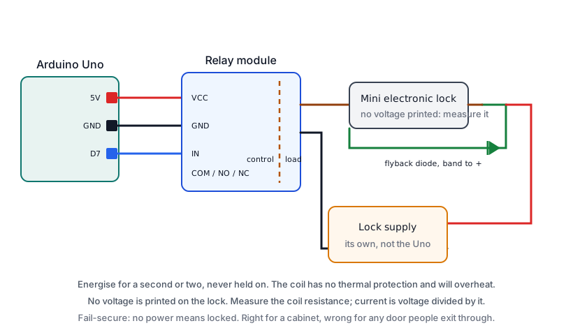
Wiring steps
- Unplug everything. Measure the coil resistance and work out the current.
- Check your supply can deliver that current with headroom.
- Control side only: Arduino to the relay, and confirm it clicks with nothing on the contacts.
- Unplug. Load side: supply positive to
COM,NOto the lock’s red wire, lock black to supply negative. - Fit the diode across the lock’s wires, banded end to red.
- Hold the lock, or clamp it. It jumps when it fires.
- Plug in the USB cable, then the lock supply.
Software and libraries
No library is required.
Minimal working example
// Siratek: open a lock for a fixed moment, and never longer.

const int lockPin = 7;
const int buttonPin = 2;

// Relay polarity: see Switching Bigger Loads with a Relay.
const int LOCK_ENERGISED = LOW;
const int LOCK_RESTING   = HIGH;

// How long the bolt is held in.
const unsigned long OPEN_FOR = 1500;

// A hard ceiling, checked independently of anything else.
const unsigned long ABSOLUTE_MAX = 3000;

bool energised = false;
unsigned long energisedAt = 0;

void release() {
  if (!energised) {
    return;
  }
  energised = false;
  digitalWrite(lockPin, LOCK_RESTING);
  Serial.println("lock released");
}

void openLock() {
  if (energised) {
    return;                       // already open; do not extend the time
  }
  energised = true;
  energisedAt = millis();
  digitalWrite(lockPin, LOCK_ENERGISED);
  Serial.println("lock energised");
}

void setup() {
  digitalWrite(lockPin, LOCK_RESTING);    // before pinMode
  pinMode(lockPin, OUTPUT);
  pinMode(buttonPin, INPUT_PULLUP);

  Serial.begin(9600);
  Serial.println("Siratek: press the button to open.");
}

void loop() {
  // Two independent limits. The second cannot be reasoned away by a bug
  // in whatever decided to open the lock.
  if (energised && millis() - energisedAt >= OPEN_FOR) {
    release();
  }
  if (energised && millis() - energisedAt >= ABSOLUTE_MAX) {
    Serial.println("absolute limit reached");
    release();
  }

  if (digitalRead(buttonPin) == LOW) {
    openLock();
  }
}
openLock() refuses to extend an open that is already running. Without that, holding the button or a sensor that keeps triggering would keep pushing the timestamp forward and the lock would stay energised indefinitely, which is precisely what must not happen.
The two limits are separate on purpose. The first is the normal one; the second exists in case something is wrong with the first. On a part that can be destroyed by being left on, that redundancy is worth four lines.
Opening on a card
The point of the lock is to be opened by something. With the RFID reader:
// Siratek: open the lock for a recognised card.
// See Reading RFID Cards with an RC522 for the honest limits of this.

void loop() {
  if (energised && millis() - energisedAt >= OPEN_FOR) {
    release();
  }

  if (!reader.PICC_IsNewCardPresent() || !reader.PICC_ReadCardSerial()) {
    return;
  }

  if (isAllowed(reader.uid)) {
    Serial.println("card accepted");
    openLock();
  } else {
    Serial.println("card refused");
  }

  reader.PICC_HaltA();
  reader.PCD_StopCrypto1();
}
Note that the release check runs before the card reading, so a card presented during the open period cannot delay the release.
What happens when the power goes
Test this deliberately, because it is the behaviour you are relying on.
Energise the lock, and while it is open, pull the lock’s supply. The bolt should spring back out immediately. That is fail-secure working, and it is why this lock belongs on a cabinet and not on a room door.
Expected result
A firm click and a visible movement of the bolt, about a second and a half, then a click as the spring returns it.
Hold the lock when you first fire it: the impulse is sharper than you expect, and an unclamped lock will jump off the bench.
Nothing should get warm. If the lock is warm after a few operations, it is being held on too long, and the run-time limit is not doing its job.
Troubleshooting
| Symptom | Likely cause | Check or fix |
|---|---|---|
| Nothing moves, relay clicks | Supply voltage or current | Measure at the lock’s own wires |
| Bolt moves weakly | Supply sagging | Needs 0.5 to 1.5 A; check the rating |
| Lock gets hot | Held energised too long | That is what the limits prevent |
| Lock hot despite the limits | Something calls openLock() repeatedly |
It refuses to extend; check the logic |
| Relay contacts pit quickly | No flyback diode | 1N4007 across the coil, banded end positive |
| Arduino resets when it fires | Shared supply | Separate supply, grounds joined |
| Lock jumps off the bench | Normal; it is an impulse | Clamp or screw it down |
| Bolt does not return | Mechanical binding, or still energised | Check the alignment and the release |
| Door stays locked after a power cut | Fail-secure, as designed | Do not use this on a door people exit through |
| Opens for the wrong card | Accepting any match | See the RFID tutorial on UIDs |
Next steps
- Easier first: Switching Bigger Loads with a Relay, which this page depends on.
- Related products: the RC522 reader or the fingerprint sensor, to decide who gets in, and their notes on what those are and are not suitable for.
- Next project: an RFID door lock on a cabinet, with the card check, the run-time limit and a log of who opened it.
Sources and attribution
All text, wiring guidance and code in this tutorial are original Siratek work.
- The two-wire lock with its small connector, the sliding bolt, the four-slot mounting plate and the absence of any voltage marking were read from the Siratek product photographs for item 2795.
- Relay switching, the startup behaviour and the safety scoping are as set out in Switching Bigger Loads with a Relay.
Because no voltage is printed on the part, this tutorial gives a measurement method rather than a figure, and the bench session should record what the supplier actually ships. Current and duty-cycle guidance follows from how small solenoid locks are built rather than from a datasheet for this specific part. The fail-secure behaviour and its consequences for escape routes are stated as a limitation of scope. No third-party tutorial text, diagrams, photographs or code has been reproduced here.