

01
Nov
Controlling an SG90 Servo
Draft. This tutorial has not been checked against the physical product yet. Confirm wiring, pin assignments and voltage limits against the product documentation before building it.
| Difficulty | Intermediate |
|---|---|
| Category | Motion |
| Supported boards | Arduino Uno R3 and compatible ATmega328P boards |
| Time needed | 45 minutes |
| Prerequisites | Powering Your Project |
| Tested board | Not yet verified |
| Tested on | Not yet verified |
| Arduino IDE version | Not yet verified |
| Library | Not yet verified |
What it does
A hobby servo is a small geared motor with a position sensor and a control circuit inside. You do not tell it to turn; you tell it where to be, and it drives itself there and holds.
That is the whole idea, and it is the reason a servo is usually the right first moving part. A plain DC motor spins at whatever speed the voltage gives it and has no idea where it is. A servo goes to 90 degrees and stays at 90 degrees, pushing back if something tries to move it.
The SG90 is the small blue one, about nine grams, with a lead of three wires ending in a female header. It rotates through roughly 180 degrees.
Before you begin
Required parts and tools
- An Arduino Uno or compatible board.
- One SG90 micro servo. This is Siratek product 2754.
- Three male-to-male jumper wires, to go into the servo’s female header.
- For anything beyond the first test: a separate 5 V supply, such as four AA cells or a USB power bank with a breakout.
The horns and the small screw in the bag are the plastic arms that fit the output shaft. Fit one before testing, so you can see the movement.
The three wires
| Wire colour | What it is |
|---|---|
| Brown, sometimes black | Ground |
| Red | Power, 5 V |
| Orange, sometimes yellow or white | Signal |
Brown to GND, red to 5V, orange to a digital pin. The colours on the Siratek part are brown, red and orange, with the signal wire on the outside edge of the connector.
Reversing power on a servo can destroy it immediately, and the connector will happily go on backwards. Check the colours against the table before plugging in.
Powering it, which is the part most tutorials skip
An SG90 draws a few tens of milliamps turning freely. Stalled, or starting a movement under load, it can draw several hundred.
The Uno’s 5V pin cannot supply that. What happens is not a clean failure: the servo starts to move, the supply voltage dips, the ATmega328P browns out and resets, and the board starts again. To the reader it looks like the code is crashing, and no amount of reading the sketch will find it.
So:
- One small servo, moving slowly, nothing else connected, on USB power: fine for a first test. That is what the example below is.
- Anything real — two servos, a servo under load, a servo alongside a display or sensors — needs its own 5 V supply.
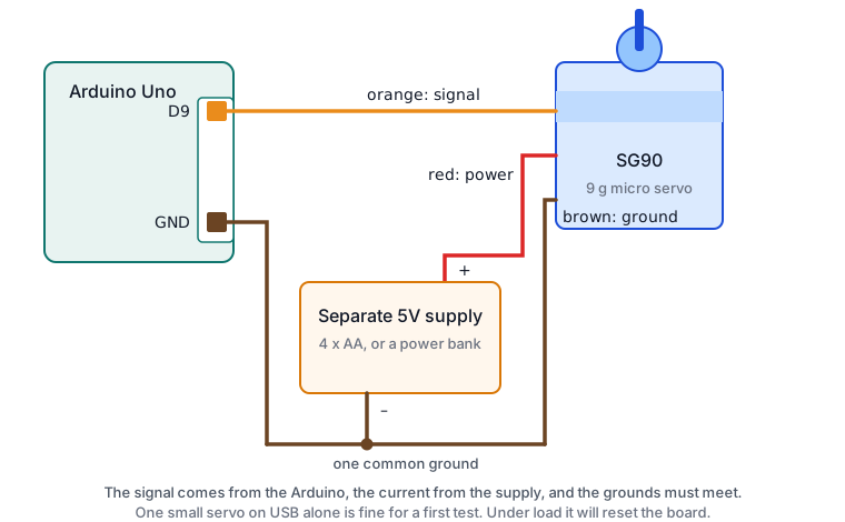
When you give it one, join the grounds. The servo’s supply ground and the Uno’s GND must be connected, or the signal has no shared reference and the servo twitches at random. This is the single most common fault with separately powered servos, and it looks like a broken servo.
Power from the separate supply goes to the servo’s red wire. The signal still comes from the Arduino. The Arduino’s 5V pin is not involved at all.
What the signal actually is
A servo is not controlled by voltage or by PWM duty cycle in the usual sense. It expects a pulse roughly every 20 milliseconds, and the width of that pulse sets the position: about 1.0 millisecond for one end of the travel, about 1.5 for the middle, about 2.0 for the other end.
The Servo library generates those pulses for you, which is why the sketch below is three lines long. It is worth knowing what is underneath, because it explains two things you will meet: why any digital pin works rather than only the PWM-marked ones, and why the library quietly takes over a hardware timer.
Pin reference
| Wire | Connect to | Purpose | Notes |
|---|---|---|---|
| Brown | Uno GND |
Ground | And to the separate supply’s ground, if used |
| Red | Uno 5V, or a separate 5 V supply |
Power | Separate supply for anything beyond a first test |
| Orange | Uno D9 |
Signal | Any digital pin works |
Wiring steps
For the first test, on USB power only:
- Unplug the USB cable.
- Fit a horn to the servo’s output shaft so the movement is visible.
- Brown wire to
GND. - Red wire to
5V. - Orange wire to
D9. - Plug the USB cable back in. The servo may twitch once as the pin settles. That is normal.
For anything more, replace step 4: red wire to the separate supply’s positive, and run a wire from that supply’s ground to the Uno’s GND.
Software and libraries
Servo ships with the Arduino IDE. Nothing to install.
It is worth knowing what it costs you. On an Uno the library uses Timer1, which is the timer behind analogWrite() on pins 9 and 10. So as soon as a sketch includes Servo.h and attaches a servo, those two pins stop working as PWM outputs, whether or not the servo is on either of them.
If an LED on pin 9 or 10 stops dimming the moment you add a servo, this is why, and the fix is to move the LED to pin 3, 5, 6 or 11. Dimming and Speed Control with PWM covers which timer drives which pin.
Minimal working example
// Siratek: sweeping an SG90 servo.

#include <Servo.h>

Servo arm;

void setup() {
  arm.attach(9);
}

void loop() {
  arm.write(0);
  delay(1000);

  arm.write(90);
  delay(1000);

  arm.write(180);
  delay(1000);

  arm.write(90);
  delay(1000);
}
write() takes an angle in degrees. The servo goes there as fast as it can and holds.
The delay() calls are not the servo moving; they are you waiting for it. The library returns immediately and the servo takes its own time, roughly a tenth of a second per sixty degrees on an SG90. Ask for a new position before it has arrived and it simply changes course.
Moving at a chosen speed
Because write() always moves at full speed, a controlled sweep means stepping the angle yourself.
// Siratek: a smooth sweep, without blocking the rest of the sketch.

#include <Servo.h>

Servo arm;

int angle = 0;
int step = 1;
unsigned long lastMove = 0;

const int moveInterval = 15;  // milliseconds per degree

void setup() {
  arm.attach(9);
  arm.write(angle);
}

void loop() {
  if (millis() - lastMove >= moveInterval) {
    lastMove = millis();

    angle += step;
    if (angle >= 180 || angle <= 0) {
      step = -step;
    }

    arm.write(angle);
  }

  // Other work can happen here. Nothing is blocked.
}
This is the millis() pattern from Timing Without delay(), applied to movement. Larger moveInterval gives a slower sweep.
Finding the real limits
write(0) and write(180) are nominal. Real SG90s vary, and asking for an angle past the mechanical stop makes the servo push against it and buzz, drawing stall current the whole time. That is how servos get hot and how gears get stripped.
// Siratek: find the usable range of your own servo.
// Watch and listen. Back off as soon as it buzzes or strains.

#include <Servo.h>

Servo arm;

void setup() {
  Serial.begin(9600);
  arm.attach(9);
  Serial.println("Siratek: type an angle and press Enter.");
}

void loop() {
  if (Serial.available() > 0) {
    int angle = Serial.parseInt();
    if (angle >= 0 && angle <= 180) {
      arm.write(angle);
      Serial.print("moved to ");
      Serial.println(angle);
    }
  }
}
Creep up from 90 towards each end. When the servo buzzes and stops moving, you have found the stop. Note the two numbers and keep your project a few degrees inside them.
Expected result
A visible movement to each position, with a short whirr, and then silence. A servo that is holding position and not loaded should be quiet.
Continuous buzzing means it is fighting something: a mechanical stop, a horn pressing against the case, or a demanded angle it cannot reach. Buzzing is not normal and should be investigated rather than ignored.
Troubleshooting
| Symptom | Likely cause | Check or fix |
|---|---|---|
| Board resets when the servo moves | Current beyond the supply | Separate 5 V supply, grounds joined |
| Twitches at random, never settles | Separate supply, grounds not joined | Join the supply ground to Uno GND |
| No movement at all | Signal wire on the wrong pin | Orange to the pin named in attach() |
| No movement, servo warm | Power reversed | Check brown to GND, red to 5 V |
| Buzzes continuously | Pushed against a stop | Find the real range; stay inside it |
| Moves but will not reach 0 or 180 | Normal part variation | Use the range you measured |
| Jitters slightly while holding | Normal for a cheap servo | Detach when idle if it matters |
| LED on pin 9 or 10 stops dimming | Servo has taken Timer1 |
Move the LED to 3, 5, 6 or 11 |
| Second servo makes both misbehave | One supply, not enough current | Separate supply sized for both |
| Gets hot after a few minutes | Holding against a load | Reduce the load, or detach between moves |
Next steps
- Easier first: Powering Your Project, which is the background to everything above.
- Related product: the MG90S, Siratek 2758, the same size with metal gears and more torque.
- Next project: drive the angle from a potentiometer, which makes the servo follow a knob.
Sources and attribution
All text, wiring guidance and code in this tutorial are original Siratek work.
- Arduino core documentation for the
Servolibrary and its use of Timer1 on the Uno. - The three-wire lead and colour order described here were read from the Siratek product photographs for item 2754.
Current draw, pulse widths and the usable angular range vary between individual servos, and are given here as typical values with a procedure for measuring your own. No third-party tutorial text, diagrams, photographs or code has been reproduced here.