

01
Nov
Project, a Gas Leak Alarm
Draft. This tutorial has not been checked against the physical product yet. Confirm wiring, pin assignments and voltage limits against the product documentation before building it.
| Difficulty | Advanced |
|---|---|
| Category | Projects |
| Supported boards | Arduino Uno R3 and compatible ATmega328P boards |
| Time needed | 120 minutes |
| Prerequisites | Smoke and Gas Sensing with MQ-2 |
| Tested board | Not yet verified |
| Tested on | Not yet verified |
| Arduino IDE version | Not yet verified |
| Library | Not yet verified |
What you will build
A box that watches the air near an LPG cylinder, sounds an alarm when the level rises, latches until somebody acknowledges it, switches on a fan, and tells you plainly when it cannot be trusted.
Read this first, before you build it or give it to anybody
This is not a gas detector. It is a project about building one.
Smoke and Gas Sensing with MQ-2 sets out why, and the reasons do not go away because the sensor is now in a box with a buzzer:
- It is not calibrated and cannot be. The reading says the level went up. It cannot say by how much, and any sketch printing “ppm” from this module is printing a number with no basis.
- It cannot tell you which gas it is. LPG, alcohol vapour, cooking smoke and a cleaning cloth all move the same reading.
- It depends on a working Arduino. A crashed sketch, a loose wire or a flat supply reports nothing at all, silently.
- A certified detector is tested, approved and designed to fail audibly. This is a learning component on a breadboard.
LPG cylinders are in most kitchens in Kumasi and a leak is genuinely dangerous. Build this for the understanding, and buy a certified detector for the kitchen. If you give this project to someone, say that sentence to them as well, because a box with a flashing light and a siren looks much more authoritative than it is.
With that said: nearly everything that makes a real alarm trustworthy can be learned here, and the design below takes those parts seriously.
Before you begin
Parts
| Part | Siratek product | Its own tutorial |
|---|---|---|
| Arduino Uno | 2219 | Getting Started with Arduino Uno |
| MQ-2 gas sensor | 2949 | Smoke and Gas Sensing with MQ-2 |
| Passive buzzer | 8051 | Play Tones with a Passive Buzzer |
| Two-channel relay module | 3398 | A Two-Channel Relay Module |
| Green, amber and red LEDs with 220 ohm resistors | 2234 | Your First Circuit, an LED and a Resistor |
| Push button | 2353 | Read a Push Button |
| Breadboard and jumper wires | Using a Breadboard |
Burn the sensor in first, and do it now
A new MQ-2 drifts considerably over its first 24 to 48 hours of continuous power. Any threshold you choose before that will be wrong afterwards.
So before you write a line of code: wire VCC and GND, leave the module powered on a shelf for a day or two, and come back. This is the step everyone skips, and it is why a gas alarm that worked on Monday reports nonsense on Tuesday.
Separately, every power-up needs two to three minutes of preheat. The sketch below enforces that rather than trusting you to wait.
Where it goes, which decides whether it works at all
LPG, propane and butane are heavier than air. They pool at floor level. Mount the sensor around thirty centimetres from the floor, near the cylinder, and a sensor on a shelf at head height may never see a leak at all.
Methane and natural gas are the opposite case and collect at the ceiling. If you are watching for those, the sensor goes high up.
Either way, keep it away from the cooker itself. Cooking fumes will trigger it constantly, and an alarm that cries wolf gets unplugged, which is worse than no alarm.
What the relay is and is not for
Channel 1 drives a warning lamp or sounder — something louder and more visible than a buzzer on a breadboard.
Channel 2 drives a fan, to ventilate.
Neither channel shuts off a gas supply. A solenoid valve on a gas line is plumbing and safety work, needs the right valve and the right installation, and is not something to drive from a breadboard project with an uncalibrated sensor. If that is what you want, it is a job for somebody qualified.
Read A Two-Channel Relay Module before wiring the load side. Two things from it matter here: the yellow jumper decides whether the optocouplers isolate anything, and the relays in the Siratek photographs are marked with a 12 V coil voltage while the product is listed as 5 V, so read the printing on your own board before connecting it.
The failure that matters most
Think about what this project does when the sensor wire falls off.
An analog input with nothing connected floats. It will read something, that something will look like clean air, and the project will sit there with a green light reporting that all is well. A safety device that fails silently into “everything is fine” is worse than no device, because it is trusted.
So the sketch checks that the reading is plausible — not stuck at zero, not pinned at 1023, not frozen at exactly the same value for minutes on end — and treats implausibility as a fault with its own distinct signal. That is most of the difference between a demonstration and something built with care.
How it works
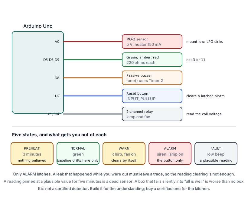
Five states, and the transitions between them are the project:
| State | Lights | Sound | What ends it |
|---|---|---|---|
PREHEAT |
Amber, slow blink | Silent | Three minutes |
NORMAL |
Green | Silent | A rise past the warn threshold, or a fault |
WARN |
Amber | Short chirp every few seconds | Rise clears, or it gets worse |
ALARM |
Red | Continuous two-tone | Only the reset button |
FAULT |
Red, fast blink | Distinct repeated beep | The reading becomes plausible again |
Three design decisions sit inside that table.
The alarm latches. Once in ALARM it stays there until a person presses the button, even if the reading returns to normal. A self-clearing alarm means a leak that happened while you were out left no trace, and the one thing you most want to know is that it happened.
The warn level does not latch. Something briefly raising the reading — a match, a cleaning cloth — should chirp and pass. Only a real rise should take it further.
The baseline is frozen above NORMAL. The MQ-2 page explains why: a slowly drifting baseline absorbs a slow leak and the alarm quietly clears itself. While anything is happening, the baseline stops moving.
Why a baseline rather than a fixed threshold
The raw reading depends on temperature, humidity and the sensor’s age as well as on gas. A fixed threshold chosen on a cool morning triggers by itself on a hot afternoon.
Comparing against a slowly updated average of the recent past removes all of that. What the project reacts to is a rise, which is what a leak looks like, and the long-term drift it ignores is what the weather looks like.
Build it in stages
Stage 1: watch the raw numbers for an hour
With the sensor burnt in, run the MQ-2 tutorial’s example and let it print. Note the baseline in your room, how much it moves over an hour, and how far it jumps when you hold an alcohol-dipped cotton bud near the mesh.
Those three numbers give you WARN_RISE and ALARM_RISE. A rise comfortably larger than the hour’s natural wander, and comfortably smaller than the cotton bud, is the window you want.
Stage 2: the indicators
Three LEDs and the buzzer, no sensor logic. Drive each state by hand from the serial monitor until you can tell all five apart from across the room without reading anything.
This sounds like a detour. It is not: an alarm whose states look alike is an alarm nobody can interpret under pressure.
Stage 3: the relay, control side only
Wire DC+, DC-, In1 and In2, with nothing on the contacts, and confirm you hear each channel click. Then wire the load side, having read the coil voltage printed on your own relays.
Stage 4: put it together
The complete sketch below, with PREHEAT_MS shortened to ten seconds while you test, then set back.
Pin reference
| Device | Pin | Connect to | Notes |
|---|---|---|---|
| MQ-2 | AO |
Uno A0 |
The reading |
| MQ-2 | DO |
Not connected | The trimmer threshold is not used |
| MQ-2 | VCC |
Uno 5V |
Heater, about 150 mA continuously |
| MQ-2 | GND |
Uno GND |
|
| Buzzer | + |
Uno D8 |
tone() uses Timer 2 |
| Buzzer | - |
Uno GND |
|
| Green LED | anode | Uno D5 |
Through 220 ohms |
| Amber LED | anode | Uno D6 |
Through 220 ohms |
| Red LED | anode | Uno D9 |
Through 220 ohms |
| Button | one leg | Uno D2 |
INPUT_PULLUP |
| Button | other leg | Uno GND |
|
| Relay | DC+, DC- |
Uno 5V, GND |
Or its own coil supply; see its page |
| Relay | In1 |
Uno D7 |
Warning lamp or sounder |
| Relay | In2 |
Uno D4 |
Fan |
No LED is on pin 3 or 11. tone() takes over Timer 2, which is what produces PWM on those two pins, so anything dimmed there stops responding while the buzzer sounds. The passive buzzer page explains it; here it is the reason for the pin choice.
The complete sketch
// Siratek: a gas leak alarm, built as a learning project.
// This is not a certified detector. See the note at the top of the page.

const int gasPin    = A0;
const int buzzerPin = 8;
const int greenPin  = 5;
const int amberPin  = 6;
const int redPin    = 9;
const int resetPin  = 2;
const int lampPin   = 7;      // relay channel 1
const int fanPin    = 4;      // relay channel 2

// Relay polarity: see A Two-Channel Relay Module.
const int RELAY_ON  = LOW;
const int RELAY_OFF = HIGH;

// ---- Measured in YOUR room, after burn-in. See stage 1. ----
const int WARN_RISE  = 60;
const int ALARM_RISE = 140;
// Implausible readings. An unplugged sensor sits near one end.
const int PLAUSIBLE_LOW  = 20;
const int PLAUSIBLE_HIGH = 1000;
// ------------------------------------------------------------

const unsigned long PREHEAT_MS = 180000UL;   // three minutes
const unsigned long SAMPLE_EVERY = 500;
const unsigned long STUCK_AFTER = 300000UL;  // five identical minutes is a fault

enum State { PREHEAT, NORMAL, WARN, ALARM, FAULT };
State state = PREHEAT;

float baseline = 0;
const float smoothing = 0.995;

int raw = 0;
int rise = 0;

int lastRaw = -1;
unsigned long lastChange = 0;
unsigned long lastSample = 0;
unsigned long blinkAt = 0;
bool blinkOn = false;

void setLights(bool green, bool amber, bool red) {
  digitalWrite(greenPin, green);
  digitalWrite(amberPin, amber);
  digitalWrite(redPin, red);
}

void setup() {
  // Relays rest off, before their pins become outputs.
  digitalWrite(lampPin, RELAY_OFF);
  digitalWrite(fanPin, RELAY_OFF);
  pinMode(lampPin, OUTPUT);
  pinMode(fanPin, OUTPUT);

  pinMode(greenPin, OUTPUT);
  pinMode(amberPin, OUTPUT);
  pinMode(redPin, OUTPUT);
  pinMode(resetPin, INPUT_PULLUP);

  Serial.begin(9600);
  Serial.println(F("Siratek: gas alarm. Preheating; no alarm until this finishes."));

  lastChange = millis();
}

// Is the sensor telling us anything at all?
bool implausible() {
  if (raw < PLAUSIBLE_LOW || raw > PLAUSIBLE_HIGH) {
    return true;
  }
  if (millis() - lastChange > STUCK_AFTER) {
    return true;                     // not one count of movement in five minutes
  }
  return false;
}

void loop() {
  if (millis() - lastSample >= SAMPLE_EVERY) {
    lastSample = millis();

    raw = analogRead(gasPin);
    if (raw != lastRaw) {
      lastRaw = raw;
      lastChange = millis();
    }

    // The baseline follows the weather, and only while nothing is happening.
    if (state == NORMAL) {
      baseline = smoothing * baseline + (1.0 - smoothing) * raw;
    }
    rise = raw - (int) baseline;
  }

  // ---- Preheat. Nothing is believed during it. ----
  if (state == PREHEAT) {
    if (millis() - blinkAt >= 700) {
      blinkAt = millis();
      blinkOn = !blinkOn;
      setLights(false, blinkOn, false);
    }
    if (millis() >= PREHEAT_MS) {
      baseline = analogRead(gasPin);
      state = NORMAL;
      Serial.print(F("preheat done. baseline = "));
      Serial.println(baseline);
    }
    return;
  }

  // ---- A fault outranks everything except the alarm. ----
  if (state != ALARM && implausible()) {
    if (state != FAULT) {
      state = FAULT;
      Serial.print(F("FAULT: implausible reading "));
      Serial.println(raw);
    }
  } else if (state == FAULT) {
    state = NORMAL;
    baseline = raw;
    Serial.println(F("fault cleared"));
  }

  // ---- The reset button only ever clears a latched alarm. ----
  if (state == ALARM && digitalRead(resetPin) == LOW) {
    Serial.println(F("alarm acknowledged"));
    state = NORMAL;
    baseline = raw;                  // start again from where we are now
    noTone(buzzerPin);
  }

  // ---- Transitions ----
  if (state == NORMAL && rise > WARN_RISE) {
    state = WARN;
    Serial.print(F("WARN: rise "));
    Serial.println(rise);
  } else if (state == WARN && rise > ALARM_RISE) {
    state = ALARM;
    Serial.print(F("ALARM: rise "));
    Serial.println(rise);
  } else if (state == WARN && rise < WARN_RISE / 2) {
    state = NORMAL;
    Serial.println(F("clear"));
  }

  // ---- What each state looks and sounds like ----
  switch (state) {
    case NORMAL:
      setLights(true, false, false);
      noTone(buzzerPin);
      digitalWrite(lampPin, RELAY_OFF);
      digitalWrite(fanPin, RELAY_OFF);
      break;

    case WARN:
      setLights(false, true, false);
      digitalWrite(lampPin, RELAY_OFF);
      digitalWrite(fanPin, RELAY_ON);          // ventilate early
      if (millis() % 3000 < 120) {
        tone(buzzerPin, 1800);
      } else {
        noTone(buzzerPin);
      }
      break;

    case ALARM:
      setLights(false, false, true);
      digitalWrite(lampPin, RELAY_ON);
      digitalWrite(fanPin, RELAY_ON);
      tone(buzzerPin, (millis() % 800 < 400) ? 2400 : 1600);
      break;

    case FAULT:
      if (millis() - blinkAt >= 200) {
        blinkAt = millis();
        blinkOn = !blinkOn;
        setLights(false, false, blinkOn);
      }
      digitalWrite(lampPin, RELAY_OFF);
      digitalWrite(fanPin, RELAY_OFF);
      if (millis() % 2000 < 80) {
        tone(buzzerPin, 600);                  // low, and unlike the alarm
      } else {
        noTone(buzzerPin);
      }
      break;

    default:
      break;
  }
}
Five decisions worth explaining
Nothing is believed during preheat. The reading starts high and falls for three minutes, which looks exactly like a leak clearing. Alarming on it would be alarming on the sensor warming up, and it would happen at every power cut.
The fault check outranks the gas logic, but not the alarm. A sensor that has stopped responding cannot clear an alarm that is already sounding — that decision belongs to the person with the button.
“Stuck” is a fault, not just a range check. A reading pinned at an entirely plausible 412 for five minutes is a dead sensor or a frozen input, and the range check alone would never notice. Real air always wanders by a count or two.
The fault beep is deliberately unlike the alarm. Low, short, every two seconds, against the alarm’s loud two-tone. Someone across the room should be able to tell “it is broken” from “there is gas” without coming over to look.
Acknowledging resets the baseline to the current reading. After a real event the air takes tens of seconds to clear, and resuming with the old baseline would re-alarm immediately. Starting from where things are now is the honest choice, and it is also why the alarm had to latch: the record of what happened is the latch, not the reading.
Testing it
| Try this | It should |
|---|---|
| Power up | Amber blink for three minutes, then green |
| Alcohol-dipped cotton bud near the mesh | Amber and a chirp, then red and the siren |
| Take it away | Stay red and sounding; it has latched |
| Press reset | Green, immediately, with a new baseline |
| Press reset while green | Nothing at all |
Pull the A0 wire off |
Red fast blink and the low fault beep, within a few seconds |
Pull VCC off the sensor instead |
Fault, though it may take the five-minute stuck check |
| Leave it an hour untouched | Still green; the baseline follows the room |
| Blow out a match nearby | Warn or alarm, depending on how close |
The sixth test is the point of the project. Anyone can make a buzzer sound when a reading goes up. Making the box say “do not trust me” when its sensor falls off is the part that takes thought, and it is worth doing that test in front of whoever you built it for.
The seventh is slower on purpose and worth understanding. Unplugging VCC leaves the heater off but the analog pin still connected, so the reading may stay plausible for a while — which is exactly why the stuck check exists alongside the range check.
Making it yours
- Show the numbers. An I2C LCD with the raw reading, the baseline and the rise makes choosing thresholds much easier, and makes the project explain itself.
- Log the events. The SD card module and the DS3231: a dated line for every warn, alarm and fault. A month of that tells you whether your thresholds are right.
- Send it somewhere. The ESP32 MQTT node turns an alarm into a message on your phone. Keep the local buzzer: a notification nobody looks at is not an alarm.
- Add a second sensor. An MQ-5 alongside the MQ-2 is more specific to LPG, and two sensors agreeing is far more convincing than one. They wire identically.
- Give it a battery. A mains alarm that dies in a power cut is a project; one that keeps watching is a device. Powering Your Project has the options, and the heater’s 150 mA makes this harder than it looks.
What not to do: put a solenoid valve on the gas line from this. That is the one extension to leave to somebody qualified.
Troubleshooting
| Symptom | Likely cause | Check or fix |
|---|---|---|
| Alarms a few minutes after power-up | Preheat too short | Three minutes, and nothing believed before it |
| Alarms by itself in the afternoon | Fixed-threshold thinking | The baseline tracks it; check state == NORMAL is the only drift case |
| Never alarms, even on alcohol | WARN_RISE too high |
Print rise and watch it |
| Alarms constantly in the kitchen | Too near the cooker | Move it; it responds to many gases |
| Nothing after a real leak outside | Sensor mounted too high | LPG sinks; thirty centimetres from the floor |
| Alarm clears itself | Baseline still drifting while alarming | It must only drift in NORMAL |
| LED on pin 3 or 11 will not dim | tone() owns Timer 2 |
Use 5, 6, 9 or 10 |
| Relay does not click | Coil supply or the yellow jumper | See A Two-Channel Relay Module |
| Relay buzzes and will not pull in | A 12 V coil on 5 V | Read the printing on the relay |
| Fault state at every power-up | PLAUSIBLE_LOW above the real baseline |
Widen the window to your measurements |
| Reading drifts for a day or two | Never burnt in | 24 to 48 hours powered, once in its life |
| Board resets when the fan starts | Fan current through the Arduino’s supply | Separate supply, grounds joined |
| Everybody trusts it | The real risk | Say what it is. Fit a certified detector too |
Sources and attribution
All text, wiring guidance and code in this project are original Siratek work.
- Sensor behaviour, the preheat and burn-in periods, the 150 mA heater, the gas-density siting advice, the baseline technique and the safe testing method with alcohol are as set out in Smoke and Gas Sensing with MQ-2, which cites the MQ-2 datasheet.
- The Timer 2 conflict affecting PWM on pins 3 and 11 is as set out in Play Tones with a Passive Buzzer.
- The optocouplers, the coil-supply jumper and the coil voltage discrepancy on product 3398 are as set out in A Two-Channel Relay Module, read from the Siratek product photographs.
- The five-state design, the latching alarm, the plausibility and stuck-reading checks and the distinct fault signal are Siratek’s own design decisions for this project.
Thresholds are specific to one sensor in one room after burn-in, so the tutorial gives a procedure for measuring them rather than values to copy. This project has not yet been built and run on hardware. The limits of what this sensor can be trusted to do are stated at the top of the page and are not softened anywhere below it. No third-party tutorial text, diagrams, photographs or code has been reproduced here.