

01
Nov
Dimming and Speed Control with PWM
Draft. This tutorial has not been checked against the physical product yet. Confirm wiring, pin assignments and voltage limits against the product documentation before building it.
| Difficulty | Intermediate |
|---|---|
| Category | Concepts |
| Supported boards | Arduino Uno R3 and compatible ATmega328P boards |
| Time needed | 30 minutes |
| Prerequisites | Your First Circuit, an LED and a Resistor |
| Tested board | Not yet verified |
| Tested on | Not yet verified |
| Arduino IDE version | Not yet verified |
| Library | Not yet verified |
What this covers
A digital pin has two states, on and off. Yet analogWrite() dims an LED and slows a motor. This explains how, which pins can do it, and the three places it behaves differently from what you would expect.
Before you begin
An LED and a 220 ohm resistor on pin 9, wired as in Your First Circuit, an LED and a Resistor. Everything here can be seen on that one LED.
Switching fast instead of switching partly
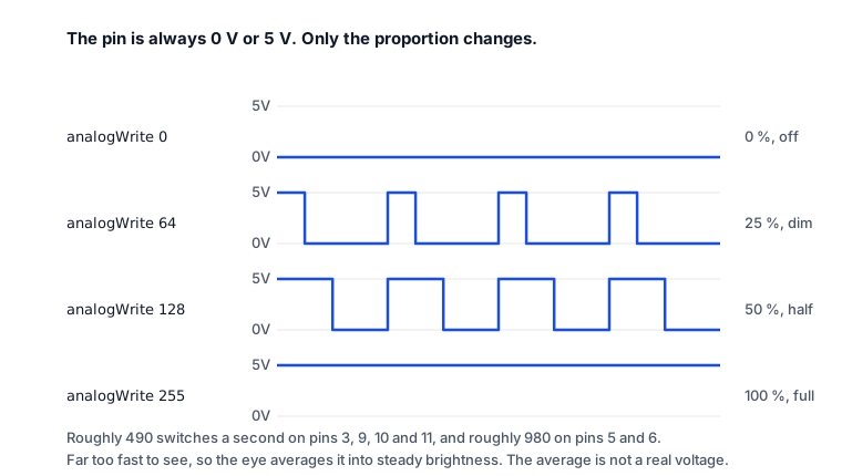
The pin never sits at a middle voltage. It switches between 0 V and 5 V, hundreds of times a second, and spends a different proportion of each cycle high.
That proportion is the duty cycle. At 25 percent the pin is high for a quarter of each cycle; the LED receives a quarter of the energy and looks dim. At 75 percent it looks bright. The switching is far too fast to see, so your eye averages it into steady brightness.
analogWrite(pin, value) sets the duty cycle, with value from 0 to 255.
analogWrite value |
Duty cycle | LED looks |
|---|---|---|
| 0 | 0 percent, always off | Off |
| 64 | 25 percent | Dim |
| 128 | 50 percent | Half |
| 191 | 75 percent | Bright |
| 255 | 100 percent, always on | Full |
The name is misleading. It is not analog output, and the Uno cannot produce a true varying voltage. It produces a square wave whose average is what you asked for.
Which pins
On an Arduino Uno, six pins only: 3, 5, 6, 9, 10 and 11. They are marked with a tilde on the board.
analogWrite() on any other pin does not produce an error. It treats anything from 128 upwards as fully on and anything below as off, which looks like a broken fade rather than a mistake. If your dimming only ever gives two brightnesses, this is why.
Three things that surprise people
The frequency is not the same on every pin
Pins 5 and 6 switch at roughly 980 Hz. The other four switch at roughly 490 Hz. Both are far too fast to see on an LED, but they matter for a motor, which can whine audibly at the lower rate, and for anything that filters or measures the signal.
Pins 5 and 6 do not quite reach zero
Those two share a timer with the Arduino core’s own timekeeping, the one millis() and delay() depend on. The interaction leaves them slightly brighter than expected at very low values, and analogWrite(5, 0) may not be completely dark.
If you need a pin to go genuinely off, use digitalWrite(pin, LOW) for that case, or put the LED on 3, 9, 10 or 11.
tone() takes pins 3 and 11 away
tone() claims the timer that drives PWM on pins 3 and 11. While a tone is playing, analogWrite() on those two does nothing useful, silently. A project that makes sounds and dims lights should put the lights on 5, 6, 9 or 10.
Minimal working example
// Siratek: what a duty cycle looks like.
// Steps an LED through five brightness levels, naming each one.

const int ledPin = 9;

const int levels[] = { 0, 64, 128, 191, 255 };
const int percent[] = { 0, 25, 50, 75, 100 };
const int levelCount = 5;

void setup() {
  pinMode(ledPin, OUTPUT);
  Serial.begin(9600);
  Serial.println("Siratek: stepping through duty cycles.");
}

void loop() {
  for (int i = 0; i < levelCount; i++) {
    analogWrite(ledPin, levels[i]);

    Serial.print("value=");
    Serial.print(levels[i]);
    Serial.print("  duty=");
    Serial.print(percent[i]);
    Serial.println("%");

    delay(1200);
  }
}
Stepping through fixed levels shows the relationship far better than a smooth fade, because you can hold each one and compare.
Driving it from a potentiometer
analogRead() gives 0 to 1023 and analogWrite() wants 0 to 255, so the value has to be rescaled.
const int potPin = A0;
const int ledPin = 9;

void loop() {
  int reading = analogRead(potPin);
  analogWrite(ledPin, map(reading, 0, 1023, 0, 255));
  delay(20);
}
Dividing by four would also work, and is what map() effectively does here. Use map() anyway: it states the intent, and it keeps working when one of the ranges changes.
What PWM can and cannot drive
PWM suits anything that responds to average power: LED brightness, small motor speed, heater output, a servo’s control signal.
It does not suit anything that needs a steady voltage, such as a reference for a sensor or an audio level. For those you need a real digital-to-analog converter, or a filter to smooth the square wave into a level.
And the pin’s current limit has not changed. A motor still needs a transistor or a driver module between the pin and the load, whatever the duty cycle. PWM controls when the current flows, not how much the pin can supply.
Check yourself
analogWrite(7, 128)on an Uno. What does the LED do?- Why might a motor whine on pin 9 but not on pin 5?
- Your sketch plays a tone and dims an LED on pin 11. The LED stops dimming. Why?
- Does
analogWrite(9, 128)put 2.5 V on pin 9?
Answers in order: pin 7 has no PWM, so 128 and above is fully on and the LED is simply lit. Pin 9 switches at about 490 Hz, which is within hearing; pin 5 runs at about 980 Hz. tone() has taken the timer that drives pin 11. No, the pin is still switching between 0 V and 5 V; 2.5 V is only the average.
Troubleshooting
| Symptom | Likely cause | Check or fix |
|---|---|---|
| Only two brightnesses | Not a PWM pin | Use 3, 5, 6, 9, 10 or 11 |
| Will not go fully off on pin 5 or 6 | Timer shared with the core timing | Use digitalWrite() for off, or another pin |
| Dimming stopped when sound started | tone() holds pins 3 and 11 |
Move the output to 5, 6, 9 or 10 |
| Motor whines | 490 Hz switching is audible | Try pin 5 or 6 |
| Fade looks uneven | Eye response, not a fault | Expected; curve the values if it matters |
| Measured voltage is wrong | A meter averages the square wave | The pin is switching, not holding a level |
Next steps
- Easier first: Your First Circuit, an LED and a Resistor.
- Next: Timing Without delay(), so a fade can run while the rest of the project works.
- Later: the servo and motor driver tutorials, which are PWM applied to movement.
Sources and attribution
All text and code in this tutorial are original Siratek work.
- Arduino core documentation and source for
analogWrite(), the PWM pin list and the timers behind them. - ATmega328P datasheet for the timer behaviour on pins 5 and 6.
No third-party tutorial text, diagrams, photographs or code has been reproduced here.