

01
Nov
Mixing 3.3 V and 5 V Safely
Draft. This tutorial has not been checked against the physical product yet. Confirm wiring, pin assignments and voltage limits against the product documentation before building it.
| Difficulty | Advanced |
|---|---|
| Category | Foundations |
| Supported boards | Arduino Uno R3, ESP32 and other mixed-voltage combinations |
| Time needed | 45 minutes |
| Prerequisites | Digital and Analog, and When Each Applies |
| Tested board | Not yet verified |
| Tested on | Not yet verified |
| Arduino IDE version | Not yet verified |
| Library | Not yet verified |
What this covers
An Uno’s pins swing to 5 V. An ESP32’s, a BMP280’s and an RC522’s swing to 3.3 V, and their inputs are not built to survive 5 V.
Connect them directly and one of three things happens: it works, it works for a while, or the 3.3 V part dies immediately. Which one you get depends on details you cannot see, and the first two are worse than the third because they teach you the wrong lesson.
This page is about knowing which direction is safe, which is not, and the three ways to fix the one that is not.
Before you begin
Required parts and tools
- A bidirectional logic level converter. This is Siratek product 8440.
- A soldering iron. Both six-pin headers are supplied loose.
- A multimeter, for checking before connecting.
- Resistors, if you take the divider route below.
Which direction is the problem
This is the part worth getting straight, because half of all mixed-voltage connections need nothing at all.
3.3 V device sending to a 5 V Arduino: usually fine. The ATmega328P reads anything above about 3.0 V as HIGH, and 3.3 V clears that. The margin is thin, which is why a long wire or a weak driver can make it unreliable, but it does no damage.
5 V Arduino sending to a 3.3 V device: this is the dangerous one. The 3.3 V part’s input is rated to about its supply plus a few tenths. Five volts is well past it, and the damage is cumulative, which is why a module can work for an hour and then stop.
So before reaching for a converter, ask which way the signal travels:
| Connection | Direction | Needs shifting? |
|---|---|---|
| Sensor’s output to Uno input | 3.3 V to 5 V | No |
| Uno output to module input | 5 V to 3.3 V | Yes |
I2C, SDA and SCL |
Both ways | Yes, see below |
SPI MISO |
3.3 V to 5 V | No |
SPI MOSI, SCK, CS |
5 V to 3.3 V | Yes |
Notice that SPI needs shifting on three lines and not on the fourth. That asymmetry is why a four-channel converter is the usual size.
I2C is a special case
I2C is open-drain: no device ever drives the bus high. Everything can only pull it low, and resistors pull it back up.
So on an I2C bus the voltage is set by whatever the pull-up resistors connect to, not by the Arduino. If a 3.3 V module has its own pull-ups to 3.3 V and the Uno adds nothing, the bus sits at 3.3 V and everybody is happy.
The complication on an Uno is that the AVR Arduino core has long enabled the ATmega’s internal pull-ups to 5 V inside Wire.begin(). Those are weak, 20 to 50 kilohms, so against a module’s 10 kilohm pull-ups to 3.3 V the bus settles somewhere in between, typically a few tenths of a volt over the 3.3 V part’s limit.
In practice a great many people run 3.3 V I2C sensors on an Uno this way and never see a problem. In specification terms it is out of bounds. For a project you intend to keep, use the converter.
The three ways to shift a level
1. A resistor divider, for one direction
Two resistors from the 5 V output to ground, with the 3.3 V input taken from the junction. For 5 V down to 3.3 V, roughly 1 kilohm and 2 kilohms, with the 2 k to ground.
- Cheap, and you already have the parts.
- One direction only, and it has to be an output on the 5 V side.
- Slow on anything fast, because the resistance and the wire’s capacitance form a filter. Fine for serial at 9600, marginal for SPI.
Good enough for a single line such as a Bluetooth module’s RXD.
2. The converter module, for everything else
The Siratek part is a four-channel bidirectional board, and it is the right default.
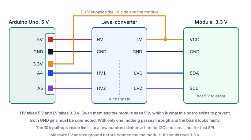
The silkscreen reads HV1 HV2 HV HV3 HV4 GND along one side and LV1 LV2 LV GND LV3 LV4 along the other.
HVtakes the high voltage, 5 V from the Uno.LVtakes the low voltage, 3.3 V from the Uno’s3.3Vpin or from the module’s supply.- Both
GNDpins must be connected, to a common ground. - Channels pair up:
HV1withLV1, and so on.
Inside each channel is a small MOSFET with a 10 kilohm pull-up on each side, and that arrangement is what makes it bidirectional without any direction pin.
It is not fast. Those 10 k pull-ups and the MOSFET limit it to a few hundred kilohertz comfortably. That is plenty for I2C and for serial; it is not enough for SPI at full speed, and an SD card or a display that works at 1 MHz may fail at 8. If an SPI device misbehaves through one of these, slow the clock before suspecting the wiring.
3. Use a 3.3 V board instead
The real answer for anything with several 3.3 V parts.
An ESP32 is 3.3 V throughout, so a BMP280, an RC522 and an OLED all connect directly with no converter, no dividers and nothing to get wrong. It also costs less than a Mega.
If you find yourself fitting two converters to an Uno, the board is the thing to change.
Pin reference
| Converter pin | Connect to | Purpose |
|---|---|---|
HV |
Uno 5V |
High-side supply |
GND (high side) |
Uno GND |
Common ground |
HV1 to HV4 |
Uno signal pins | 5 V side of each channel |
LV |
Uno 3.3V, or the module’s supply |
Low-side supply |
GND (low side) |
Common ground | Both grounds are needed |
LV1 to LV4 |
The 3.3 V device | 3.3 V side of each channel |
Wiring steps
- Unplug the USB cable.
- Solder both six-pin headers to the converter.
HVto the Uno’s5V.LVto the Uno’s3.3V.- Both
GNDpins to the common ground. - Each signal: the 5 V end to an
HVchannel, the 3.3 V end to the matchingLVchannel. - Before connecting the 3.3 V module, plug in the USB and measure
LVagainst ground. It should read about 3.3 V. If it reads 5 V, the supplies are swapped and connecting the module would destroy it. - Unplug, connect the module, plug back in.
Step 6 takes thirty seconds and is the whole reason a multimeter is in the parts list.
Software and libraries
None. This is a wiring problem, and no sketch can compensate for it.
Minimal working example
There is nothing to run, so here is the check instead: measure, do not assume.
// Siratek: a square wave to probe the converter with.
// Put a meter or a scope on the LV side; it should swing about 0 to 3.3 V.

const int testPin = 7;

void setup() {
  pinMode(testPin, OUTPUT);
  Serial.begin(9600);
  Serial.println("Siratek: 1 Hz square wave on pin 7. Measure HV1, then LV1.");
}

void loop() {
  digitalWrite(testPin, HIGH);
  delay(500);
  digitalWrite(testPin, LOW);
  delay(500);
}
Wire pin 7 to HV1 and measure LV1 with a meter. At one hertz an ordinary multimeter will follow it, showing roughly 0 V and 3.3 V alternately.
If LV1 follows at 5 V, the converter is not doing anything, and the usual reason is LV being fed from the wrong place.
Expected result
LV measuring about 3.3 V against ground. A signal driven high on the HV side appearing at about 3.3 V on the matching LV side, and a signal driven on the LV side appearing at about 5 V on the HV side.
Troubleshooting
| Symptom | Likely cause | Check or fix |
|---|---|---|
LV measures 5 V |
Supplies swapped | HV is 5 V, LV is 3.3 V |
| Nothing passes through | A GND not connected |
Both grounds are needed |
| Signal passes but at 5 V | Channel bypassed, or wrong pins | HV1 pairs with LV1 |
| Works at low speed, fails fast | The 10 k pull-ups limit it | Slow the SPI clock |
| SD card fails through a converter | Same cause | Power the card module at 5 V instead |
| I2C works without a converter | Open-drain, pulled up to 3.3 V | It is out of spec, not wrong |
| 3.3 V sensor output not read by the Uno | Thin margin, or a long wire | That direction needs no shifting; shorten the wire |
| Module died after working an hour | Cumulative 5 V damage | This is what the converter prevents |
| Divider output not 3.3 V | Wrong resistor ratio | 1 k and 2 k, with the 2 k to ground |
| Two converters on one Uno | The board is the problem | Use an ESP32 |
Next steps
- Easier first: Digital and Analog, and When Each Applies, for what a logic threshold is.
- Related products: the BMP280 and the RC522, both 3.3 V parts this page exists for.
- Next: ESP32, Your First Wi-Fi Project, where everything is 3.3 V and the problem disappears.
Sources and attribution
All text, wiring guidance and code in this tutorial are original Siratek work.
- ATmega328P datasheet for the input threshold voltages that make 3.3 V readable as HIGH.
- The four-channel bidirectional layout, the
HV/LVlabelling and the loose six-pin headers were read from the Siratek product photographs for item 8440.
The behaviour of the AVR Arduino core’s internal I2C pull-ups is a long-standing property of that core rather than of any module, and is described here as something to check rather than relied on. No third-party tutorial text, diagrams, photographs or code has been reproduced here.