

01
Nov
ESP8266 NodeMCU as a Cheaper Option
Draft. This tutorial has not been checked against the physical product yet. Confirm wiring, pin assignments and voltage limits against the product documentation before building it.
| Difficulty | Advanced |
|---|---|
| Category | Communication |
| Supported boards | NodeMCU V3 and compatible ESP8266 boards |
| Time needed | 50 minutes |
| Prerequisites | ESP32, Your First Wi-Fi Project |
| Tested board | Not yet verified |
| Tested on | Not yet verified |
| Arduino IDE version | Not yet verified |
| Library | Not yet verified |
What it does
Wi-Fi, in a board that costs less than an ESP32 and does most of what one does. The ESP8266 came first; the ESP32 is its successor.
For a project that reads one sensor and publishes it, the ESP8266 is genuinely enough, and the difference in price matters when you are building several. For anything more, the ESP32’s extra pins, memory and second core are worth the small difference.
This page assumes you have done the ESP32 tutorial and covers what is different, which is more than you might expect.
Before you begin
Required parts and tools
- One NodeMCU V3 board. This is Siratek product 2597.
- A micro USB cable that carries data.
- A 2.4 GHz Wi-Fi network.
What is on the board
The Siratek part is the V3 “LoLin” style NodeMCU: an ESP-12 module with the ESP8266 inside, a micro USB socket, a USB-serial chip, and two buttons marked RST and FLASH.
It is wider than the ESP32 DevKit and, on a standard breadboard, covers every hole on both sides. That is a practical nuisance worth knowing before you plan a layout: either use two breadboards side by side, or female jumper leads straight onto the pins.
The pin numbering trap
This is the thing that wastes the afternoon, so it comes first.
The D numbers printed on the board are not the GPIO numbers the chip uses. They are a NodeMCU convention, and they do not match.
| Silkscreen | GPIO | Safe to use? |
|---|---|---|
D0 |
16 | Yes, but no interrupt and no PWM |
D1 |
5 | Yes. Often used for I2C SCL |
D2 |
4 | Yes. Often used for I2C SDA |
D3 |
0 | Pulled up; must not be LOW at boot |
D4 |
2 | Pulled up; onboard LED; must not be LOW at boot |
D5 |
14 | Yes |
D6 |
12 | Yes |
D7 |
13 | Yes |
D8 |
15 | Pulled down; must not be HIGH at boot |
RX, TX |
3, 1 | USB serial; leave them alone |
In Arduino code the constants D1, D2 and so on are defined, so digitalWrite(D1, HIGH) works. But any library or example that wants a raw GPIO number means the right-hand column. Writing 5 gets you D1; writing D5 gets you GPIO 14. Mixing the two conventions in one sketch is how people end up with a pin that seems to do nothing.
The safe pins to reach for first: D1, D2, D5, D6, D7. That is five, which is the real pin budget of this board.
One analog input, and it is odd
There is exactly one, marked A0.
On a bare ESP8266 the converter reads 0 to 1 volt. NodeMCU boards fit a divider so A0 accepts 0 to 3.3 V, which is what you want, and analogRead() returns 0 to 1023 as on an Uno rather than the ESP32’s 0 to 4095.
So it is 10-bit like an Uno, 3.3 V like an ESP32, and there is only one of it. If your project needs two analog sensors, this is not the board.
Everything else that differs from an ESP32
| ESP8266 | ESP32 | |
|---|---|---|
| Cores | One | Two |
| Clock | 80 MHz, 160 optional | 240 MHz |
| RAM available to a sketch | Roughly 40 KB | Roughly 300 KB |
| Analog inputs | One, 10-bit | Several, 12-bit |
| Bluetooth | No | Yes |
| Usable GPIO | About five | About twenty-five |
| Hardware serial ports | One and a half | Three |
The RAM figure is the one that bites. It is far more than an Uno, and far less than an ESP32, and TLS connections in particular are memory hungry.
The watchdog you cannot turn off
The ESP8266 runs Wi-Fi work in the background between passes of your loop(). If your code does not return promptly, that work does not happen and the board resets itself.
So a long loop is not merely slow here; it is a crash. Anything that takes more than a few tens of milliseconds should either be broken up or should call yield() to let the background work run.
for (long i = 0; i < 1000000; i++) {
  doSomething();
  if ((i & 0xFF) == 0) {
    yield();                   // give the Wi-Fi stack a turn
  }
}
delay() calls yield() internally, which is why a sketch full of delay() survives and a tight loop does not. It is the opposite of the usual advice and worth remembering.
Pin reference
| Pin | Purpose | Notes |
|---|---|---|
D1 (GPIO 5) |
General purpose, or I2C SCL |
|
D2 (GPIO 4) |
General purpose, or I2C SDA |
|
D5 to D7 |
General purpose | GPIO 14, 12, 13 |
A0 |
The only analog input | 0 to 3.3 V, 0 to 1023 |
3V3 |
3.3 V out | Output, not input |
VIN |
5 V in | Through the regulator |
GND |
Ground | Several |
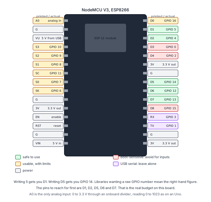
Wiring steps
Nothing to wire for this tutorial. Plug in the USB cable.
Software and libraries
Add the ESP8266 board package once, the same way as the ESP32:
- File, Preferences, add the ESP8266 package URL published in the esp8266/Arduino documentation.
- Boards Manager, search
esp8266, install. - Tools, Board, choose NodeMCU 1.0 (ESP-12E Module).
- Tools, Port, choose the port. If none appears, install the USB-serial driver; V3 boards usually use a CH340, which is the same driver as an Arduino Nano.
Note that the ESP8266 and ESP32 packages are separate installs. Having one does not give you the other.
The ESP8266WiFi library comes with the package. It is not called WiFi.h, which is the first compile error people meet when copying an ESP32 sketch across.
Minimal working example
// Siratek: an ESP8266 on Wi-Fi. Note the include: not WiFi.h.

#include <ESP8266WiFi.h>

const char* ssid     = "your network name";
const char* password = "your password";

void setup() {
  Serial.begin(115200);
  delay(500);
  Serial.println();

  WiFi.mode(WIFI_STA);
  WiFi.begin(ssid, password);

  Serial.print("Siratek: connecting");
  unsigned long start = millis();
  while (WiFi.status() != WL_CONNECTED && millis() - start < 20000) {
    delay(500);
    Serial.print(".");
  }
  Serial.println();

  if (WiFi.status() != WL_CONNECTED) {
    Serial.println("failed. 2.4 GHz only, and check the password.");
    return;
  }

  Serial.print("connected: ");
  Serial.println(WiFi.localIP());
  Serial.print("free heap: ");
  Serial.println(ESP.getFreeHeap());
}

void loop() {
  delay(1000);
}
ESP.getFreeHeap() is worth printing on this board. Watching it fall over time is how you catch a memory leak before it becomes a weekly reset, and there is much less headroom here than on an ESP32.
Porting an ESP32 sketch
Most of it carries across. The changes, in the order you will meet them:
| ESP32 | ESP8266 |
|---|---|
#include <WiFi.h> |
#include <ESP8266WiFi.h> |
#include <WebServer.h> |
#include <ESP8266WebServer.h> |
WebServer server(80) |
ESP8266WebServer server(80) |
analogRead() 0 to 4095 |
0 to 1023 |
| Any GPIO number | Only the five safe ones |
| Several analog pins | One |
ESP.getEfuseMac() |
ESP.getChipId() |
The MQTT tutorial’s sketch runs on this board with those substitutions, and that is a realistic use for it: a cheap node publishing one reading.
Deep sleep, which is this board’s real advantage
An ESP8266 in deep sleep draws microamps. A sensor that wakes every fifteen minutes, publishes, and sleeps again can run for months on batteries.
It needs one piece of wiring: D0 (GPIO 16) must be connected to RST, because that is how the chip wakes itself. Without that wire it sleeps and never returns.
// Publish, then sleep for fifteen minutes. D0 must be wired to RST.
ESP.deepSleep(15 * 60 * 1000000ULL);
Everything restarts from setup() on waking; nothing in RAM survives. Structure the sketch as “do the job once, then sleep” rather than as a loop.
One caution: with D0 wired to RST, uploading can fail, because the reset line is held. Disconnect that wire while programming and reconnect it afterwards.
Expected result
An IP address within a few seconds, and a free heap figure in the tens of thousands.
If the serial monitor shows rubbish before the first line, that is the bootloader printing at 74880 baud, which is an unusual rate this chip uses. It is not a fault, and the output becomes readable once your sketch calls Serial.begin(115200).
Troubleshooting
| Symptom | Likely cause | Check or fix |
|---|---|---|
| No serial port | CH340 driver missing | Same driver as an Arduino Nano |
| Rubbish before your first line | Bootloader prints at 74880 | Normal; ignore it |
WiFi.h not found |
Wrong include | ESP8266WiFi.h |
| A pin seems to do nothing | D number against GPIO number | D1 is GPIO 5, not GPIO 1 |
| Board resets in a long loop | Background Wi-Fi starved | Call yield() |
| Resets under TLS | Not enough heap | Use plain MQTT, or an ESP32 |
| Will not boot with a sensor attached | A boot-sensitive pin held | Avoid D3, D4, D8 for inputs |
| Analog reads four times smaller than expected | 10-bit, not 12 | 0 to 1023 here |
| Covers the whole breadboard | It is that wide | Two breadboards, or female leads |
| Never wakes from deep sleep | D0 not wired to RST |
Add the wire |
| Upload fails after adding that wire | Reset line held | Disconnect it while programming |
Next steps
- Easier first: ESP32, Your First Wi-Fi Project, which this page builds on.
- Related: Sending Sensor Data with MQTT, which runs on this board with small changes.
- Next project: a battery sensor node that wakes, publishes and sleeps.
Sources and attribution
All text, wiring guidance and code in this tutorial are original Siratek work.
- esp8266/Arduino documentation for the
ESP8266WiFiinterface, theyield()requirement, deep sleep and theD0toRSTwiring. - ESP8266 datasheet for the analog input range and the boot-mode pin constraints.
- The V3 board layout, its micro USB socket and its
RSTandFLASHbuttons were read from the Siratek product photographs for item 2597.
The GPIO mapping table is the NodeMCU convention rather than anything defined by the chip. Free heap figures vary with the libraries in use and are given as something to watch rather than a specification. No third-party tutorial text, diagrams, photographs or code has been reproduced here.