

01
Nov
ESP32, Your First Wi-Fi Project
Draft. This tutorial has not been checked against the physical product yet. Confirm wiring, pin assignments and voltage limits against the product documentation before building it.
| Difficulty | Advanced |
|---|---|
| Category | Communication |
| Supported boards | ESP32 DevKit, 30-pin |
| Time needed | 70 minutes |
| Prerequisites | Mixing 3.3 V and 5 V Safely |
| Tested board | Not yet verified |
| Tested on | Not yet verified |
| Arduino IDE version | Not yet verified |
| Library | Not yet verified |
What it does
An ESP32 is an Arduino-compatible board with Wi-Fi and Bluetooth built into the chip. It is faster than an Uno by about fifteen times, has over two hundred times the RAM, and costs less than a Mega.
This page gets you from a board in a bag to a sketch connected to your Wi-Fi, and spends most of its length on the five things that are different from an Uno. Those differences are why the library teaches the Uno first: the ESP32 is not harder, but it introduces several new ways to be confused at once.
Before you begin
Required parts and tools
- One ESP32 development board. This is Siratek product 2590.
- A micro USB cable that carries data, not just power.
- Your Wi-Fi network name and password. 2.4 GHz only; see below.
What is on the board
The Siratek part is the common 30-pin DevKit: an ESP32-WROOM-32 module, a micro USB socket, a regulator, and two buttons marked EN and BOOT.
The USB-to-serial chip is a CP2102, which the photographs show. That matters because it needs its own driver on Windows and macOS, and it is a different driver from the CH340 found on most Nanos. If no port appears when you plug the board in, this is the first thing to check.
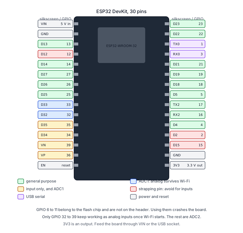
Fifteen pins down each side, labelled with GPIO numbers.
2.4 GHz only
The ESP32 has no 5 GHz radio. If your router broadcasts one network name for both bands, the board may simply fail to find it.
This is the single most common “my ESP32 will not connect” cause, and no amount of checking the password will fix it. Either give the 2.4 GHz band its own name in the router, or connect to a phone hotspot for testing.
Five differences from an Uno
1. It is 3.3 V, and not 5 V tolerant. Every pin. A 5 V sensor output into an ESP32 pin can damage it. See Mixing 3.3 V and 5 V Safely, which exists mainly for this board.
The flip side is pleasant: 3.3 V parts such as the BMP280 and the RC522 connect directly, with no converter at all.
2. Pin numbers are the chip’s GPIO numbers. The silkscreen may say D4, but in code it is 4. There is no separate analog numbering either: GPIO 34 is 34 whether you are reading it digitally or with analogRead().
3. analogRead() returns 0 to 4095, because the converter is 12-bit rather than 10-bit. Any Uno sketch that assumes 1023 reads about a quarter of what it should.
4. Some pins are special, and some are traps:
| Pins | What to know |
|---|---|
34, 35, 36, 39 |
Input only. No pinMode(OUTPUT), no internal pull-up |
6 to 11 |
Connected to the flash chip. Using them crashes the board |
0, 2, 12, 15 |
Strapping pins: the level at boot decides how the board starts |
1, 3 |
TX0 and RX0, used by the USB serial |
GPIO 2 |
Usually the onboard LED |
Safe general-purpose pins to reach for first: 4, 5, 13, 14, 16, 17, 18, 19, 21, 22, 23, 25, 26, 27, 32, 33.
5. Half the analog pins stop working when Wi-Fi is on. This is the one that wastes an afternoon.
The ESP32 has two analog converters. ADC2 is used by the Wi-Fi radio, so any analogRead() on an ADC2 pin returns nothing useful once Wi-Fi starts. The sensor is fine and the wiring is fine.
ADC1 pins, which keep working: 32, 33, 34, 35, 36, 39. Use those for anything analog on a networked project, and the problem never arises.
Powering it
- USB for development, as usual.
VINtakes 5 V and goes through the onboard regulator.3V3is an output, not an input. Do not feed it.
Wi-Fi transmission draws current in bursts, a few hundred milliamps. A thin USB cable or a weak port shows up as a board that resets when it starts transmitting, which looks like a software crash. A short, decent cable fixes more ESP32 problems than it has any right to.
Pin reference
| Pin | Purpose | Notes |
|---|---|---|
VIN |
5 V in | Through the regulator |
3V3 |
3.3 V out | Output only |
GND |
Ground | Several on the board |
GPIO 2 |
Onboard LED | Used by the example below |
GPIO 32 to 39 |
ADC1 analog inputs | Keep working with Wi-Fi on |
EN button |
Reset | |
BOOT button |
Hold during upload if needed |
Wiring steps
Nothing to wire for this tutorial. Plug in the USB cable.
Software and libraries
The ESP32 is not in the IDE by default. Add it once:
- File, Preferences, and in Additional Board Manager URLs add Espressif’s ESP32 package URL, which is published in Espressif’s own Arduino-ESP32 documentation.
- Tools, Board, Boards Manager, search for
esp32and install the Espressif package. - Tools, Board, choose ESP32 Dev Module.
- Tools, Port, choose the port that appeared. If none did, install the CP2102 driver.
Record the version of the ESP32 board package you installed. Its behaviour has changed between major versions, more than the AVR core ever does.
The WiFi library comes with the package. Nothing else to install.
Minimal working example
// Siratek: connect an ESP32 to Wi-Fi and report what happened.

#include <WiFi.h>

const char* ssid     = "your network name";
const char* password = "your password";

const int ledPin = 2;

void setup() {
  pinMode(ledPin, OUTPUT);
  Serial.begin(115200);
  delay(500);

  Serial.println();
  Serial.print("Siratek: connecting to ");
  Serial.println(ssid);

  WiFi.mode(WIFI_STA);
  WiFi.begin(ssid, password);

  // Give up after about twenty seconds rather than hanging for ever.
  unsigned long start = millis();
  while (WiFi.status() != WL_CONNECTED && millis() - start < 20000) {
    delay(500);
    Serial.print(".");
  }
  Serial.println();

  if (WiFi.status() != WL_CONNECTED) {
    Serial.println("failed.");
    Serial.println("  Check the network is 2.4 GHz, and check the password.");
    return;
  }

  Serial.print("connected. IP address: ");
  Serial.println(WiFi.localIP());
  Serial.print("signal strength: ");
  Serial.print(WiFi.RSSI());
  Serial.println(" dBm");
}

void loop() {
  digitalWrite(ledPin, WiFi.status() == WL_CONNECTED);
  delay(500);
}
Three details worth noticing.
115200, not 9600. The ESP32’s bootloader prints at 115200, and matching it means you see the boot messages too. A serial monitor at 9600 shows a screen of rubbish, which looks like a dead board.
The connection attempt gives up. while (WiFi.status() != WL_CONNECTED) with no timeout is in every example and hangs for ever on a wrong password, with no clue. Twenty seconds and an error message is more useful.
WIFI_STA makes the board join your network rather than create one. The default is sometimes both, which is rarely what you want.
Writing down the IP address
The address printed is how everything else reaches the board, so it matters.
It also changes. Your router hands out addresses from a pool and may give a different one after a reboot. For anything permanent, either reserve an address for the board’s MAC in the router, or use mDNS so the board answers to a name:
#include <ESPmDNS.h>

if (MDNS.begin("siratek-sensor")) {
  Serial.println("also reachable at http://siratek-sensor.local");
}
That works from most phones and computers on the same network, and survives the address changing.
Finding out what the board can see
When a connection fails and you are sure the password is right, this settles it:
// Siratek: list the networks the board can actually see.

#include <WiFi.h>

void setup() {
  Serial.begin(115200);
  WiFi.mode(WIFI_STA);
  WiFi.disconnect();
  delay(100);

  Serial.println("Siratek: scanning.");
  int found = WiFi.scanNetworks();

  if (found == 0) {
    Serial.println("  nothing found at all.");
  }

  for (int i = 0; i < found; i++) {
    Serial.print("  ");
    Serial.print(WiFi.SSID(i));
    Serial.print("   ");
    Serial.print(WiFi.RSSI(i));
    Serial.println(" dBm");
  }
}

void loop() {
}
If your network is not in that list, the board cannot see it, and the password was never the problem. Nine times in ten the network is 5 GHz.
Expected result
Dots while connecting, then an IP address and a signal strength, within a few seconds. The onboard LED stays lit while connected.
An RSSI of -50 dBm is strong and -80 is marginal. If it hovers near -80, move the board before blaming anything else.
Troubleshooting
| Symptom | Likely cause | Check or fix |
|---|---|---|
| No serial port appears | CP2102 driver missing | Install it; check the cable carries data |
| Rubbish on the serial monitor | Wrong baud rate | 115200 |
| Connects for ever, never succeeds | Network is 5 GHz | Scan for it; use a 2.4 GHz network |
| Scan finds nothing at all | Antenna or power | Try a different cable and port |
| Resets when it starts transmitting | Current burst on a thin cable | Shorter cable, better port |
| Upload fails with a connect error | Board not in bootloader | Hold BOOT while the upload starts |
analogRead() returns nothing with Wi-Fi on |
ADC2 pin | Use 32 to 39 |
| Analog values four times too small | 12-bit converter | 0 to 4095, not 1023 |
pinMode(34, OUTPUT) has no effect |
Input-only pin | Use a general-purpose pin |
| Board crashes on boot | Using GPIO 6 to 11 | Those belong to the flash chip |
| Boots differently depending on wiring | Strapping pin held at boot | Avoid 0, 2, 12 and 15 for inputs |
| 5 V sensor killed a pin | Not 5 V tolerant | Use a level converter |
| IP address changed after a reboot | Router handed out a new one | Reserve it, or use mDNS |
Next steps
- Easier first: Mixing 3.3 V and 5 V Safely, which this board makes necessary.
- Related: Serving a Page from an ESP32, the obvious next step.
- Next project: an IoT sensor node, sending a DHT22 reading over the network.
Sources and attribution
All text, wiring guidance and code in this tutorial are original Siratek work.
- Espressif ESP32 documentation for the ADC2 and Wi-Fi conflict, the input-only pins, the pins reserved for flash, the strapping pins and the 12-bit converter.
- Arduino-ESP32 documentation for the
WiFilibrary calls used. - The 30-pin DevKit layout, the micro USB socket, the
ENandBOOTbuttons and the CP2102 USB-serial chip were read from the Siratek product photographs for item 2590.
The board package URL is not reproduced here because it changes; the reader is directed to Espressif’s own documentation for the current one. No third-party tutorial text, diagrams, photographs or code has been reproduced here.